Posted: 02:20am
16 Apr 2026
 Copy link to clipboard Copy link to clipboard |
Solar Mike
Guru

|
|
|
Just about to wire up another low frequency 48v inverter to our 3 banks of batteries; the inverter has no internal mechanism to charge up its large electro's in a safe manner other than drawing > 1000 amp surge and possibly damaging the main contactor. A pre-charge arrangement is required, although its a simple concept armed with a 25r resistor and a switch to charge the cap's up prior to turning the thing on, I cannot expect other non qualified people to do this. We have a BMS on each battery bank each with a "On Load" relay isolated contact, this pulls in if all cells in the bank are within voltage set limits. What I want is an interface, that connects to the 3 BMS's, an external on\off switch, and the run switch on the inverter front panel; this will allow turning on\off the main inverter in a controlled manner from a central point. Should the batteries go in-out of spec, start or shutdown the inverter prior to any battery supply main contactor just dropping out. Threw this together yesterday, thought it may be useful to some others, pcb is 100x100mm. Power supply and connection to inverter front panel switch. 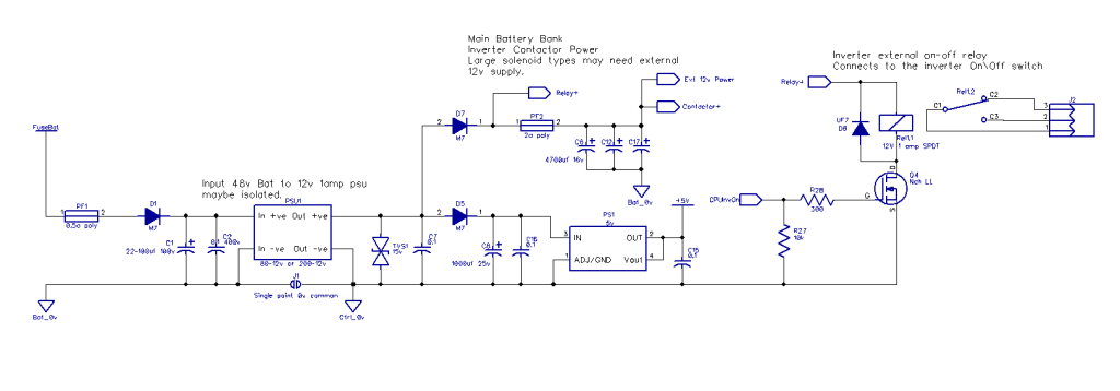 Voltage sensing of main battery bank and inverter +ve input, supply caps. 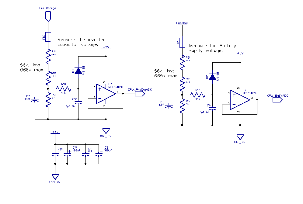 Inputs to BMS relay contacts and central on\off switch 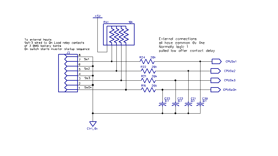 Pre-Charge mosfet high side switch and main DC contactor 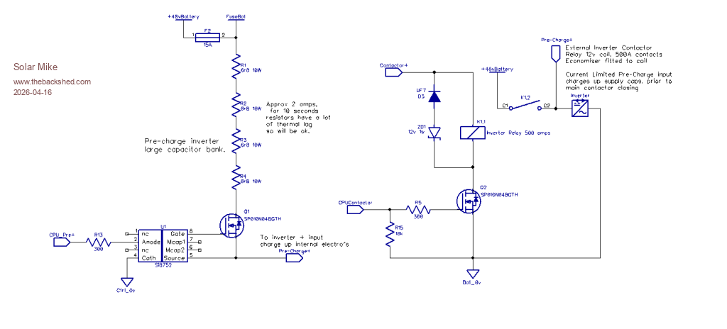 PCB 100 x 100mm: 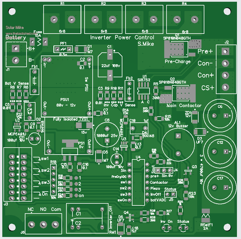 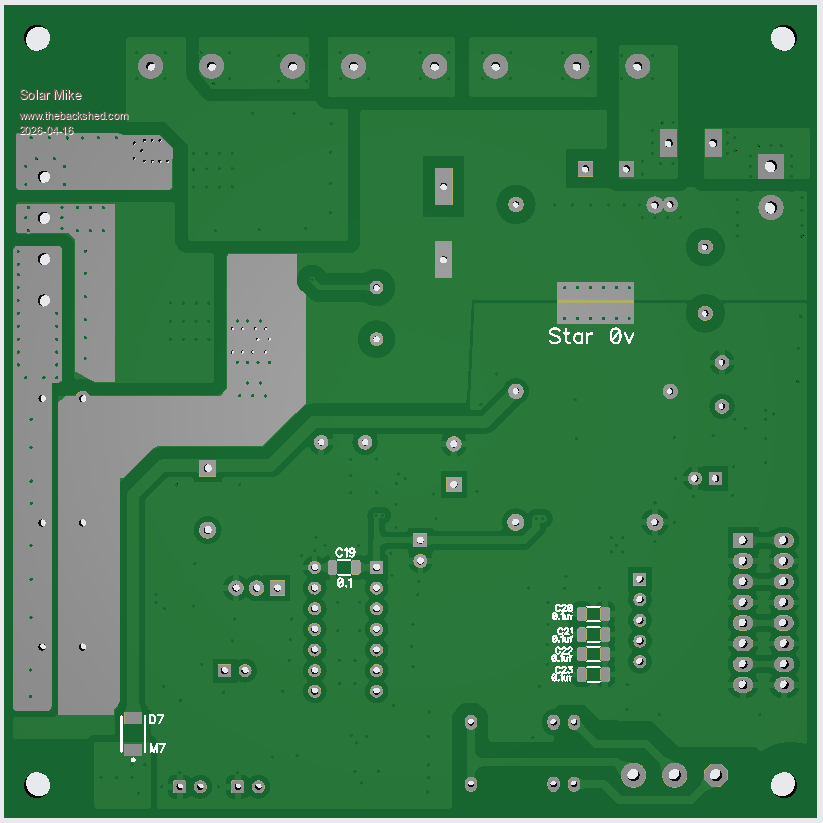 I haven't shown the cpu in the schematic, Picaxe 14M2, you can tell where it connects to, nor have I written any software for it. Anyone want the gerber files, send me a PM. Cheers Mike Edited 2026-04-16 12:22 by Solar Mike
|

