Now that the PI PICO 2 controller is out and readily available here in NZ at reasonable prices, though I would make a start at moving various projects over to it. As my projects have gotten more complex, the old Picaxe CPU's I have used in the past are proving just too slow and lacking in many features of a modern inexpensive 32 bit processor.
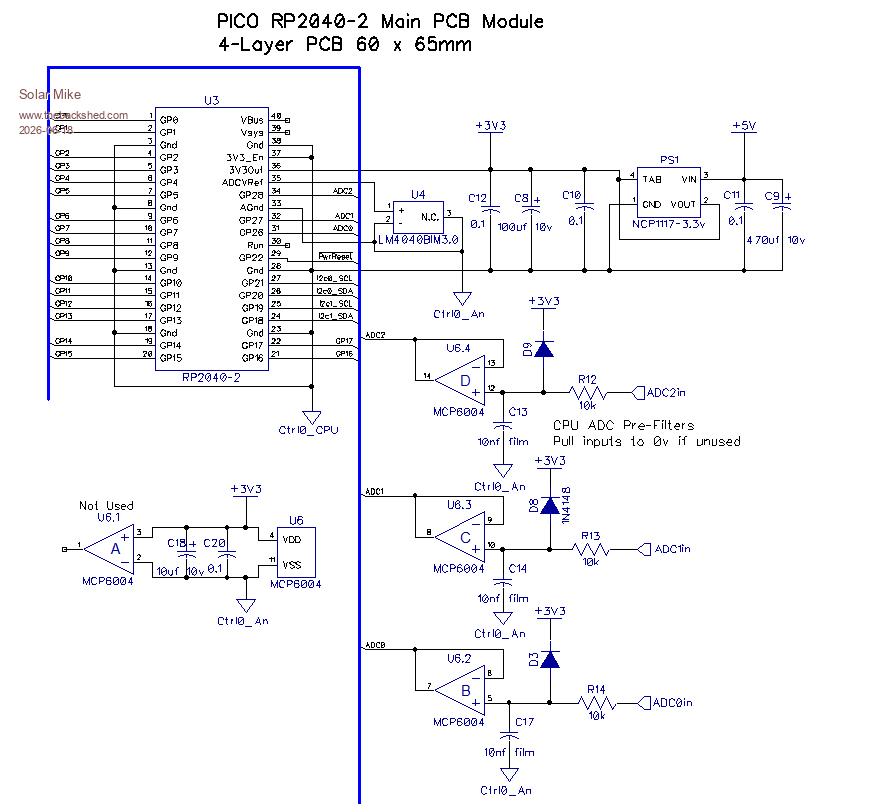
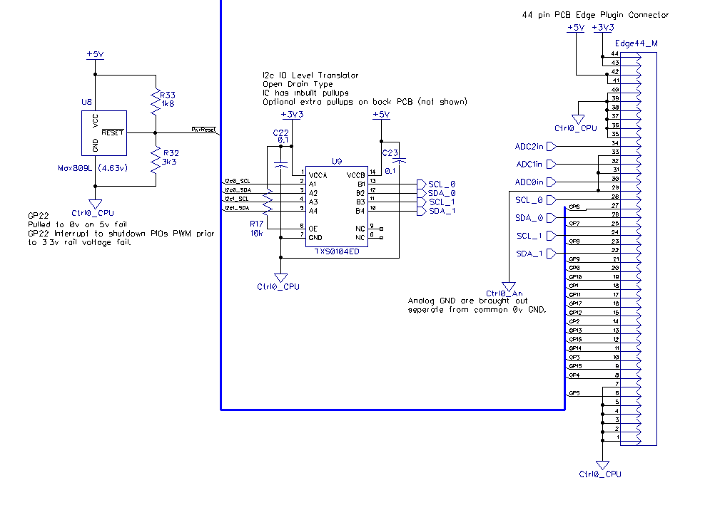
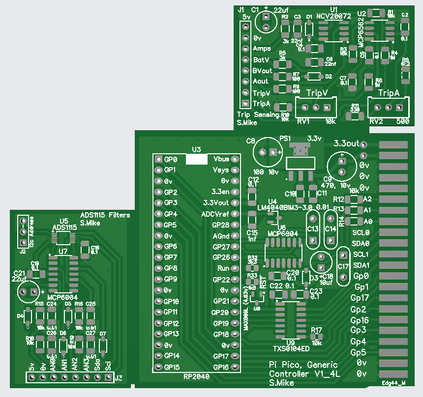
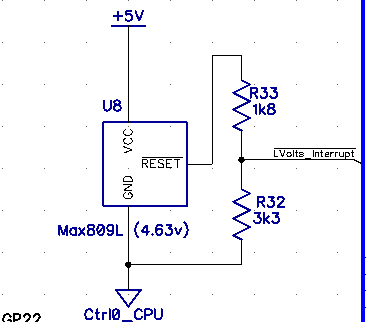
First project is a 3 phase PV charge controller; the Pico-2 PIO can easily be setup to output 3 PWM phases each running at 125 KHz and driving a buck inverter stage. To that end I want a generic plugin PCB module containing the main CPU and some ancillary components, running off a linear 3.3v psu and ADC reference of 3.0v. Included on the pcb is a voltage rail fail reset chip an MAX809L, this resets low at 4.63v, connected to the incoming 5v power it can cause a interrupt on an input pin and allow the cpu to turn off PIO output pwm signals, shutting down cleanly.
Have built this on a small 65x60mm 4-layer pcb with a 44 pin edge connector, so can be plugged in to the main PV host controller. The 4 layers give excellent internal ground and power planes which will help in a noisy inverter environment
Schematic:
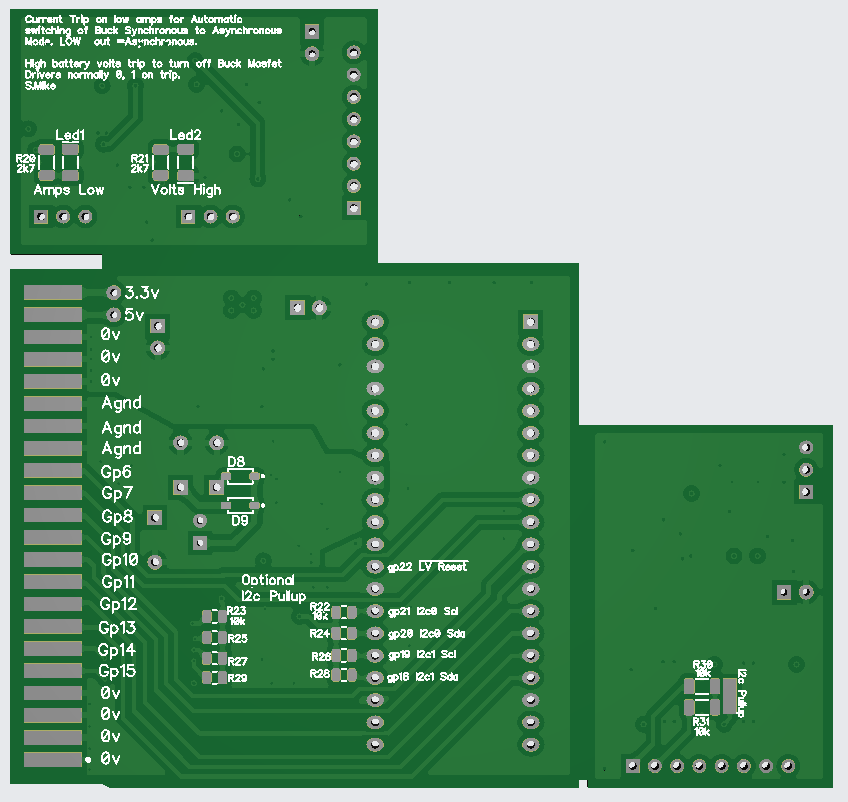
Have also made a couple of small ancillary helper modules with pin headers. These are on the same 100x100mm pcb and cut off.
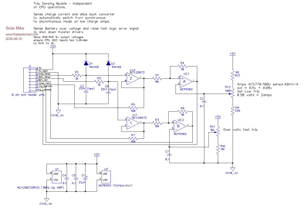
1: Trip sensing, this pcb has an over voltage detection comparator to allow shut down of the buck inverters independent of the cpu; as if the output fuse blows or battery gets suddenly disconnected the cpu sensing battery voltage cannot react fast enough to prevent the buck output voltage rising to alarming levels and perhaps destroy components.
2: Low buck current sense, at very low duty cycles its possible for the buck stages act as voltage boosters, feeding battery power backwards causing high voltages on the main capacitors, again blowing things up. To prevent this I switch off the low side synchronous rectifier mosfets at low current levels, thus turning into asynchronous rectification using the mosfets source-drain diode. CPU has no involvement here, buck stage seamlessly switches between the two modes.
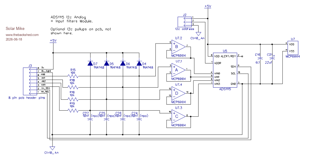
The other helper pcb has a I2c ADS1115 mux analog ADC chip and some high input impedance noise filters, again with 8 pin header, main CPU can use this to get accurate voltage measurements, as the PICO-2 still has a slightly compromised ADC input system.
100 x 100 pcb: to cut up at marked edges:
I quite like Micro Python as an object programming language, so will use that for future work using these boards, its also quite fast and allows access to the 2nd CPU, noted with strict limits.
Once I have the main CPU board working, will think about the multi-phase buck design, followed by a 230Vac inverter.
Edit: just noticed an error on the Max809, will fix it.
This is how its meant to be wired, OK on the pcb...
Cheers
Mike
Edited 2026-06-18 13:25 by Solar Mike


 I don't think I have seen any standalone chargers like it, I may have some questions later.