It's been a while since I worked on this project. I blew 2 canbus to SPI modules, the only 2 I had ($10 each or something.) So I got on to something else that needed doing.(the charge controller)
I now have 7 new canbus to SPI modules and it's time to play again.
Here is the background info:
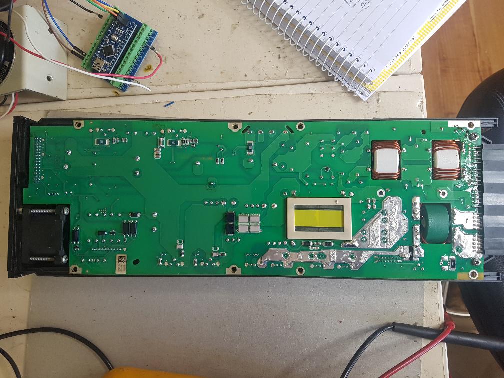
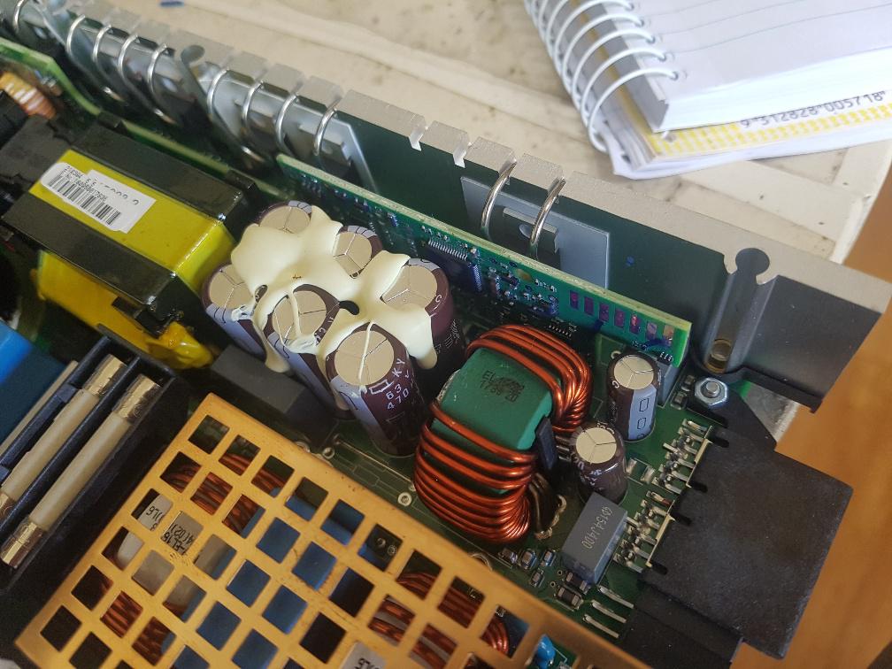
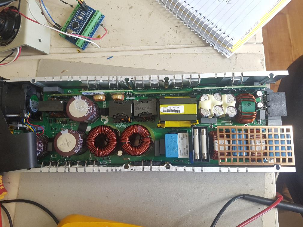
We can get Eltek 2kW HE power supplies for about $70-80 here in AUS
They are very efficient and have near 1.0 power factor.
Input is 240V AC, output 43.5 V to 57.4V with an internal 2kW output limit.
There are no user controls. All settings are done via canbus.
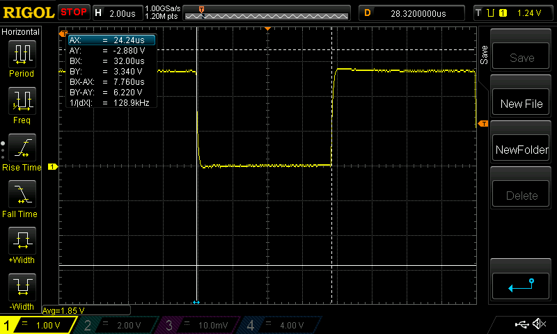
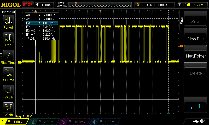
There is some information available on the canbus protocol.
Wiseguy has a need to have 2 or 3 of these PS in parallel with control over
output voltage & current in total and the individual PS.
I was talking with RenewableMark about these things and he wants to use one
as a battery charger for his 48V (ex. forklift) battery for the home solar.
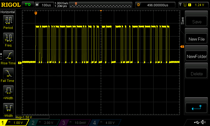
Today I want to show progress in establishing a basic understanding of control via canbus.
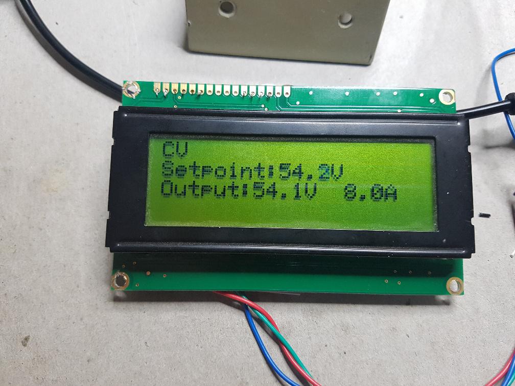
A power supply can be run in constant voltage mode (CV) or constant current mode (CC) or both. I have the Eltek working in both modes now.
First CV:
The Eltek can only output voltage in the range of 43.5 - 57.4V so there is no point
directing it to output voltages outside that range. It continues to run, but will never exceed either ends of the limit.
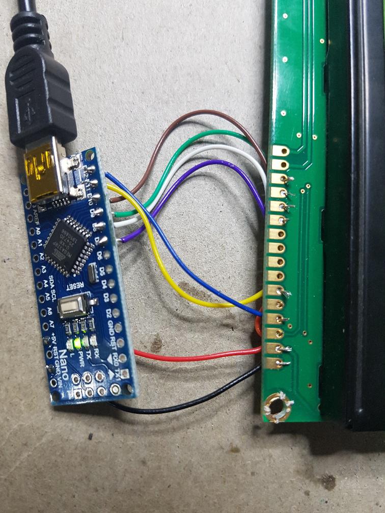
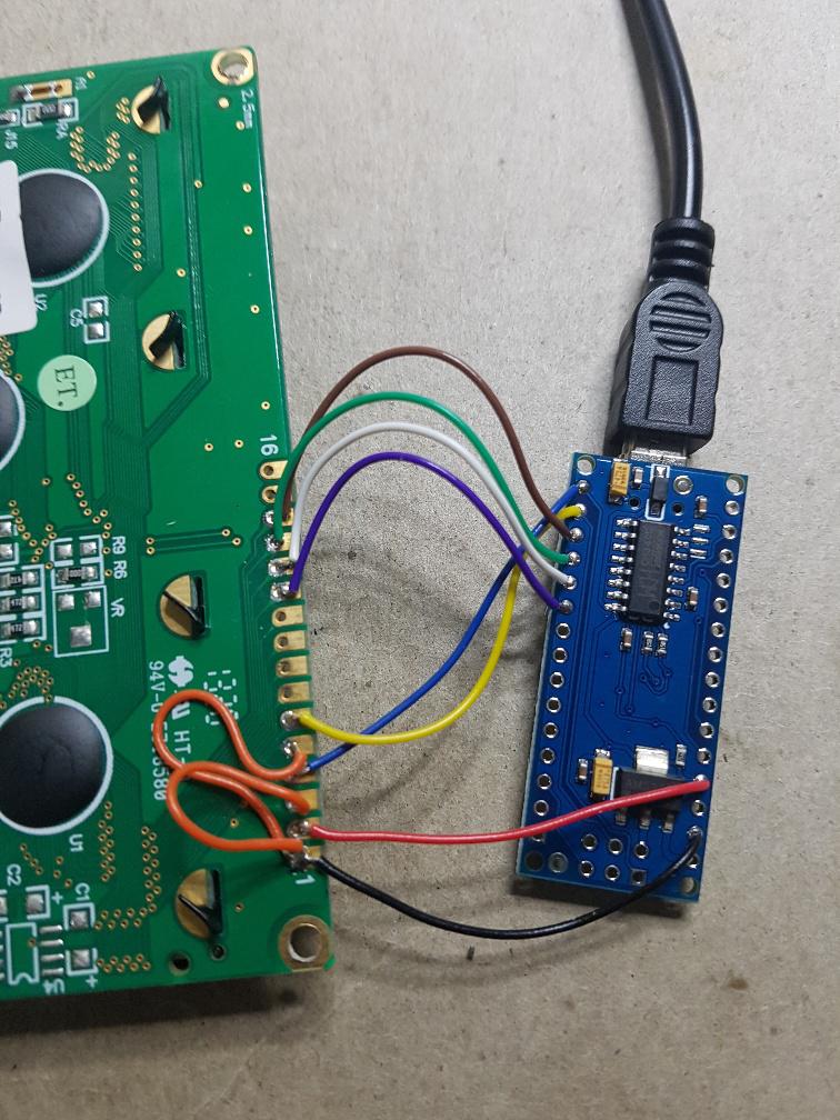
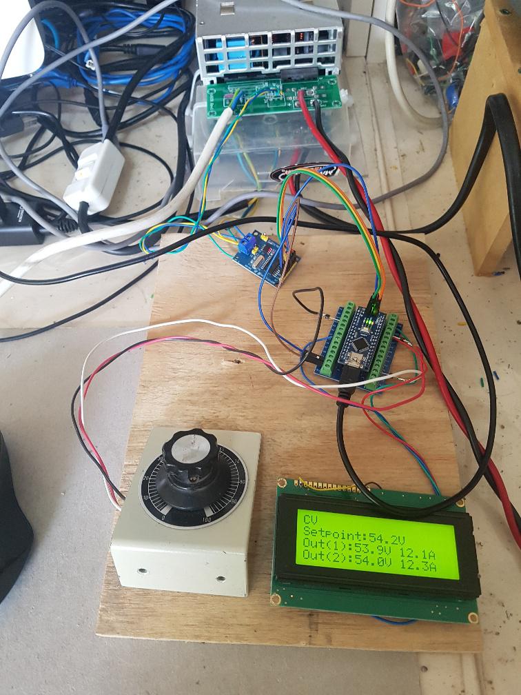
I hacked up an Arduino Uno with output voltage control via a potentiometer and it works surprisingly well. Load is a solar buck converter and the 1 Ohm 3kW bucket of water.
The code can set the output voltage of course and it can get the Eltek's operating data too, which includes output voltage and output current.
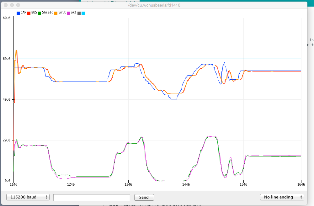
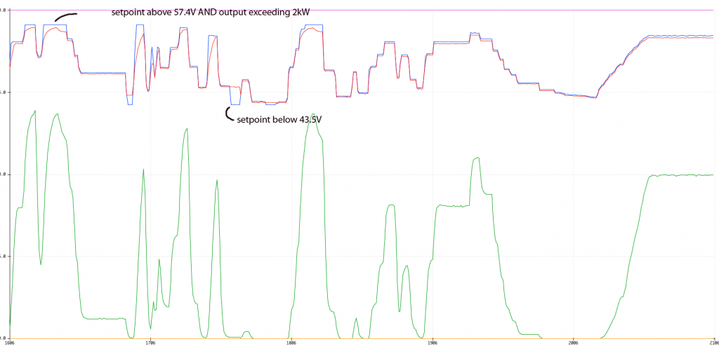
I plot the voltage setpoint, output voltage and output current below
in Blue, Red and Green. There are 500 data points in this graph and data is plotted
at about 5 Hz (5 points a second). This gives you an idea how quickly the PS can respond to changes to the setpoint.
Vertical scale is 0,15,30,45,60.
Output may exceed 2kW for a second but it is quickly brought back to 2kW by
the Eltek's control system.
I did some testing to see how the PS operates under CC.
Instead of sending a voltage setpoint, I send a current limit to the PS.
I had to modify the solar buck converter firmware to simulate a discharged battery.
The converter/simulated battery draws maximum power when input voltage is 57V and zero power when
input is 45V. This simulates a lead acid battery quite well I think and more importantly this load permits the Eltek control system to reduce the output voltage
to bring output current down to the setpoint over the entire range of values (0 Amps to 45A)
If I used a resistor I would only have a narrow range of power levels where the Eltek could control output current. The simulated battery load is very non-linear but works as it should.
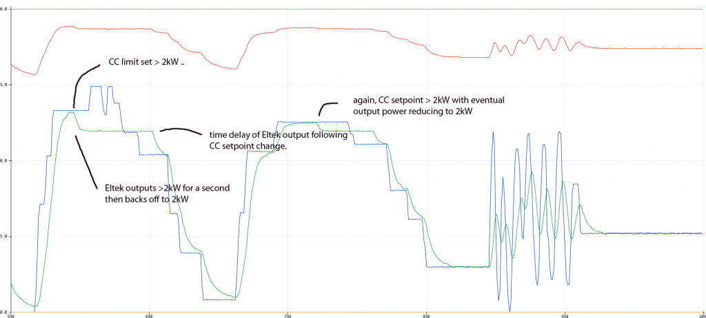
I vary the output current setpoint via a pot and we can see the Eltek track the changes.
Blue is CURRENT setpoint, Red is output voltage, Green is output current.
It appears the CC tracking is a bit slower than CV.
The above results show I can control both the output voltage and current
in the manner of a CV/CC power supply which is all we need for both Wiseguy's
and RenewableMark's projects.
This is simply a proof of concept.
The arduino code is nice and robust. It can run at all times, waiting for the Eltek to power up. Once powered, the Eltek then comes under control of the code.
I switch off the Eltek and the code is fine, waiting until the next time the Eltek is running.
Looking at the battery charger project:
The Eltek's 43.5 to 57.4V seems ideal for sealed Lead acid batteries. For flooded cells I would like a bit higher voltage to permit faster equalization.
There is a mismatch between the voltage setpoint and the output voltage as reported by the Eltek.
At 57.4V output, the difference is about -0.3V with 0.05V noise
so the output is 0.3V less than the setpoint commanded by the canbus control.
This does not change with output current.
At 43.5V it is 0.2V less than the commanded setpoint.
This difference might be due to manufacturing tolerances?
I think I could make a very nice battery charger using the Eltek and the arduino.
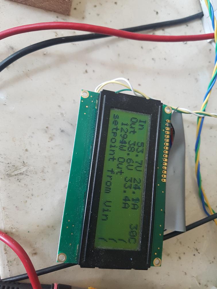
I imagine an LCD to show the status of the battery and power supply.
We program the absorb and float voltages, maybe maximum current, times to run
absorb, maybe a low current limit to automatically switch from absorb to float.
The LCD could show charge volts/current/power/amp.hours etc.