| Menu | JAQForum Ver 19.10.27 |
| Menu | JAQForum Ver 19.10.27 |
Forum Index : Electronics : Auto Transformer Queries
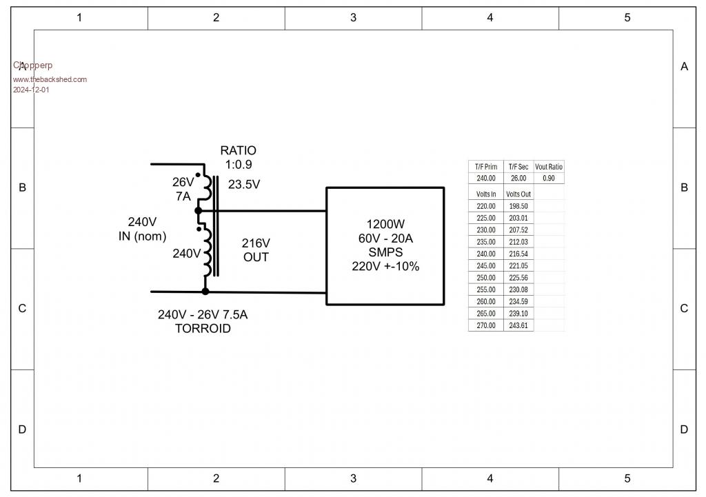
Hi I have been on the lookout for a while now for a decent DC power supply & found this one the other dayHere The only thing is that it is rated at 220V +/-10% input. At my place, the AC mains is normally 240V+ & when the sun is really shining overhead, the voltage can go above 250V. (I have solar). Today it was about 244V with cloudy conditions which is above the rated input of the supply. I did buy a SMPS a few years ago & it didn't last long with an input filter capacitor going caput. I did get a refund. I was thinking that I could reduce the input voltage by using a normal transformer (toroidal) wired as an auto-transformer as per the diagram below. (one of a couple of spares I have laying around). The transformer is a 240V to 2 x 13V @ 7.7A toroid (The secondaries shown as a single winding in the diag). From my understanding, for an auto-transformer wired as shown, the "secondary" winding carries the load current for the load while the primary just supplies the magnetising current so the primary winding size & the core size can be considerably reduced. The 7A rating should be adequate for the SMPS. The voltage table shows my calculations for the input volts & the corresponding out put from the equation:- Vout = Vin * 240/(26 + 240) = ~0.9 * Vin. This should give plenty of margin for voltage fluctuations. If the volts do drop too much, I can use just one of the 13V secondary windings. What I really want to know is that I am on the right track with with my thinking. Even better, if someone knows of a SMPS of similar capacity with a 240V rated input. Thanks Brian  Edit, Only one 'r' in Toroid Edited 2024-12-02 00:13 by Chopperp ChopperP |
||||||
As far as i can see that should work more or less exactly as you planned - and at max output of 1200w the current draw should be around 6A, which is within the rating of the transformer  |
||||||
I did exactly that apart from the transformer secondary rated at 10 amps. Used it for many years and is still in the shed waiting for the transformer to get repurposed. In my case, only one of the secondaries was used. Jim |
||||||
Thanks for the replies. Very reassuring. Measured mains volts this morning at 249V on the inverter display & 247V with my trusty RMS DMM at a nearby power point. Good voltage to let some smoke out of stuff. Brian |
||||||
don't know what you want this for but the 2kw Eltek flatpaks are superb. about 95% efficient, programmable output current and voltage ranging from about 46V to 54V and 0 to 40A. all taking a wide range of AC supply as input. I was lucky to get 2 of these for about $50 AUD. These were sourced from telcom techs who had to replace them due to old age. Later, I developed a small program to alter the output V and A to suit my needs. I use one now to charge the 400 AH 48V SLA battery I have for the house. The other is a spare, used for mppt testing. |
||||||
Are you completely off grid? It's not clear from your post. If you were off grid then there is a simpler solution, using wiseguy's VFB method in your inverter. Today I saw 2KW back charging via GTI, this increased the AC by only 2V. With the original Ozinverter VFB the same back charging would increase the inverter AC 5 times as much. I will have a few free spare PCB's for replacing the original Ozinverter VFB components with wiseguy's method, just need some testing as the boards arrived only today. |
||||||
Nah, just have a grid tied system. At the mercy of everything on line. Thanks for the input though @ poida. It's great when you can pick up stuff like that. Thanks Brian Edited 2024-12-03 06:59 by Chopperp |
||||||
Hi all Just an update... The Power Supply arrive OK & it took me a day to realise that it was actually rated at 230V +/- 10%. (I saw it on the carton first, then checked it on the supply itself). Made things easier. I actually started monitoring & recording the mean Mains Voltage plus peak & minimum & came to the conclusion that it would be safe to use as is. I did revise my circuit, switching between normal volts & mains - 13V with both secondary volts in parallel as per what Jim did. Part way building it, but so far the mains voltage has been around the 235V mark with peaks about 5V higher. So far I haven't let any smoke out of & it works well after you get used to the digital controls. I will continue to keep an eye on the mains voltage to make sure that it doesn't go too high. If it does, will press on with the build. Brian |
||||||
| The Back Shed's forum code is written, and hosted, in Australia. |