At some point I will be moving to a 100v Lifepo4 setup, requiring 32 cell monitors on each bank; and there are two banks, so 64 cells for the BMS to keep track of.
The earlier version of the BMS used a Pixaxe 08M2-LE CPU on a small module, one for each cell, all talking back to a master via opto-isolated comms; his works really well, but is time consuming to build and test. Effectively there are multiple volt meters, so calibration can be an issue.
The system I used on the three banks of 8 x 6v cell 48v lead carbon batteries was a "flying capacitor" arrangement, where a small capacitor is switched across each cell in the bank, isolated from the bank then buffered and filtered for reading the capacitor voltage by a CPU. The capacitor is discharged and the cycle repeated for every cell in the bank.
Simple in concept, single CPU volt meter, so calibration isn't an issue, using opti-mos dual mosfet relays as the selection switches, perhaps costs more but easier to build, slower than a CPU on each cell, but fast enough.
However that setup could monitor groups of 8 cells, although expandable by serial connection to another 8, took up a lot of space.
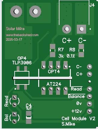
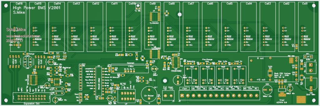
My thought now is to use the "Flying Capacitor" arrangement, with each cells monitoring components placed on a small pcb soldered to the main CPU board, similar to the "1 CPU per cell", but less parts, so easier to make. Allow 16 cells for 48v, with an expansion port for another 16 in the future.
Here is a concept Block diagram for the setup:
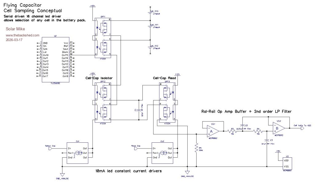
Each group of 16 cells uses a TL59282 serial input constant current shift register LED driver, each output allows selection of any cell using the AT224 opti-mos switch, a cell is selected, capacitor charged, isolated, them measured by the CPU. The timing has to be correct, to allow the switches to fully open\close and the capacitor charge to 100%. A mosfet discharges the capacitor after each measurement (not shown here), and the cycle repeats.
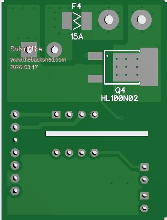
After a full scan cycle, the CPU can then turn on any balancing loads to pull down any runners, wait several seconds, turn off all loads and do another cell scan.....
Load Selection: Using another TL59282 to control the load mosfets via a TLP3906 mosfet voltage driver.
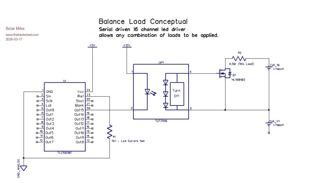
Both serial chips use the same Data,Clock,Latch signals, each chip has a Blanking or output control input and that is used to turn either chip on or off; during voltage measurement phase the loads are turned off, otherwise on if any cell requires it.
I'm working on a pcb, more later.
Mike