| Menu | JAQForum Ver 26.09 |
| Menu | JAQForum Ver 26.09 |
Forum Index : Electronics : Transformer core flux offset problem - continued.
Discussion moved from this thread as suggested by others. That is my point, no matter how big the flux imbalance between half cycles gets the full-cycle average voltage on any secondary winding is always 0V. It is the rate of change of flux that generates the voltage, not the amount of flux. For a sinewave maximum voltage is generated as the flux passes through zero, and the voltage is zero when the flux is at its peak. At the peak, for a brief moment, the flux is constant (0 rate of change) so no voltage. This is why transformers don't work on DC. The best you can hope for is the wave shape of the sensing secondary is sufficiently different when there is a flux imbalance between the two half cycles to be detected reliably. Core B-H nonlinearity might produce enough distortion but have not tested. If there is a difference, something more complicated than an integrator will be needed to detect it. Perhaps comparing the peak voltage of the half cycles may work. Scope images should show if this is practical. For testing create a predictable flux imbalance by adding another thin winding to the transformer and passing a DC current through it, from a regulated current source. The current needs to be fairly constant despite the AC voltage generated in this winding. A power supply with an adjustable current limit may be ok if the voltage limit is set higher than the p-p winding voltage. . Edited 2026-10-03 10:15 by phil99 |
||||||
Essentially I agree with your analysis and reasoning. When I have mentioned the use of an integrator to check for balance between the first and second 180° cycles, it was always to use the primary side excitation as the feed to the integrator as the output winding can only report what it can see - and it sees very poorly what is actually going on during saturation. For clarification too, to take the output voltage sense from the mains output winding especially for unbalanced loads such as heat gun half cycle loading - if we ignore any resulting saturation effects, there would be a reduction of the peak voltage for the loaded 180° half, due to ohms law. Using a sense winding should reduce the error caused by the inherent secondary impedance. When I first started playing with DC-AC conversion ~ 25 years ago I reasoned that using a DSP to look at the resulting output side response for each and every spwm cycle and modify the following duty cycle on the fly to correct for any deviation away from the expected result should work best, but to date it is just an untested theory. |
||||||
Modifying the following duty cycle on the fly in response to the primary current DC component should work well for a purely AC load current, as any DC component is then an error and needs to be corrected. For a half-wave load it is more complicated. The primary current has two components, the magnetizing current and the reflected secondary current. Flux imbalance due to DC in the secondary current is almost exactly cancelled by an equal and opposite flux imbalance produced by the reflected component of the primary current. You don't want to "correct" this. The magnetizing component of the primary current is where the problem arises. Any DC offset there can push the core toward saturation. This is what needs correcting but how do you separate the two DC components? Fortunately as KeepIS and others have shown as long as the halfwave current isn't too big it doesn't matter. |
||||||
Yes, I see the flaw in my logic. That winding can see a change in flux but it doesn't know what the baseline is supposed to be. Industrial inverters use an aux winding and an integrator, but that isn't the full picture and they are a little secretive about how they do the whole trick. What about monitoring the primary current, and since the Arduino knows what half-cycle it is in, if it sees a large current on only one polarity, it will know that the flux is walking toward saturation? Some kind of differentiation monitors the slope, di/dt, and the greater the slope, the harder the control loop pulls back? |
||||||
Yes, as noted above that will work if there is no DC component in the secondary current. With a half wave secondary load the net primary current can have two DC components. You need to correct one but not the other. How do you separate the two DC components? Perhaps also measure the instantaneous secondary current, multiply by the turns ratio, subtract that from the instantaneous primary current and what is left should be the magnetizing current. Integrate that to find the DC offset that needs correcting. Sounds like hard work. |
||||||
Yesterday, I made a bit of hardware/software that allowes me to drive a powerstage, but with the intend to introduce some drive assymetry. There is no ac feedback yet, just a fixed modulation index. But I could modify the amplitude, positive cycle amplitude, negative cycle amplitude, deadtime and frequency with a rotary encoder during operation. It looks interesting to add a setting wich makes it possible to adjust the deadtime in the pos and neg cycle apart from eachother. I use a psoc5 development board wich is easy at the moment for timerbased creation of adjustable deadtime. So I made a baseline by driving the powerboard with symetric drive. My transformer hums in that situation, wich is interesting because I assume firmware creates symetric pulses and the assymetry is created in the hardware, but it does not matter now because in the end the balancing system removes both. But actually it was a nice situation to investigate, so by setting modulation index to 0.95 on one half of the period the hum dissapeared. (Doing this on the wrong half period made it worse) So by making a 0.5% difference removed the hum but it came back so I needed to increase to 1% but this in time was a bit much, back to 0.5% and back ok, but after a few seconds not enough, so back to 1% and so on... My resolution is only per 0.5% steps, so steps of 0.1% would be more interesting, the flux offset was only in one direction. So now I could think about a measuring method to detect the offset and control it. It needs to be accurate because I can't really notice a lot imbalance on scoop images. I have allready winded some extra turns on the transformer to experiment with, the waveform does not look so pretty so a bit of light filtering will be needed. With the setup I could deliberate introduce assymetry and let it auto correct, that will be the goal. Edited 2026-10-03 16:47 by nickskethisniks |
||||||
From a paper I read a while back, I remember the wave shape asymmetry is a key indicator of flux imbalance. An integrator is unlikely to be adequate by itself. I think a filter was used in the paper to pull out mainly the second (and maybe the fifth IIRC) order harmonics before the integrator. The lab test results looked impressive but I doubted its robustness in real world systems without lots of calibration. I don't like things that rely on precision analog filters as their performance is likely to change based on component variability, aging and temperature. Edited 2026-10-04 02:57 by analog8484 |
||||||
Can you explain more why no correction should be made? For the half wave load, it seems the inverter should not drive the PWM for the unloaded half cycle nearly as much as for the loaded half cycle. I imagine this would reduce the peak flux imbalance. |
||||||
The two components of the transformer primary current can be seen better if you view a real transformer as an ideal lossless transformer with an inductor across the primary (assuming its series resistance and inductance are small). Then the inductor current is the transformer magnetizing current and the primary current is simply the load current multiplied by the turns ratio. The load determines what that current is, you can't change it without changing the output voltage. If you reduce the drive to one half cycle you will get a distorted voltage waveform. Easier to see if the ideal transformer is 1:1. Vs = Vp and Ip = Is, You could replace it with a pair of wires. The only thing left is the parallel inductor. All you need to do is ensure there is no DC through the inductor by adjusting the PWM a small amount. The low impedance of the H-bridge will give the load whatever current it demands. The PWM adjustments above mean a non-linear load will produce a little voltage distortion but you just have to put up with that. The only catch is in the real transformer you can't directly measure the inductor (magnetizing) current, making correcting it tricky. Edited 2026-10-04 07:32 by phil99 |
||||||
Wouldn't the magnetizing current be approximately the primary current minus the (secondary current x turns ratio)? Another thought I had is to use a fast comparator and just limit the peak current cycle-to-cycle. The IRF21844 gate drivers I use has a shutdown pin that could be toggled in an extreme over current event before saturation. It might be better to latch it off and let the controller turn it back on after some amount of time. |
||||||
Yes, provided the current measurements are accurate enough and read on each cycle of the PWM frequency (to cater for distorted waveforms). The magnetizing current is very small compared to the maximum primary current, 1% as a ballpark figure. So the accuracy of the transducers (not just the resolution) would need to be 0.1% to get a barely usable figure that is within +-10%, and 0.01% to get a reliable figure of within +-1% of the magnetizing current. |
||||||
This feels a bit like poking a hornets nest but I feel the need to look deeper into what is going on in our inverters The inverter power stage has impedance - it is not an ideal drive, the transformer has impedance it is not an ideal transformer, a half wave load is not an ideal load, sensing from the output voltage load winding is not the ideal way to sense. I find that trying to relate all this to an ideal transformer etc is not really very helpful in finding a solution. In laymans terms when a half wave load is connected to our inverter, yes the current drawn is reflected back to the primary. But due to the secondary impedance and to a much lesser effect the primary impedance and the impedance of the supply battery through the power stage & choke/s we have an issue. The PWM% that was being used up to the point of driving that half wave load is now not enough to drive the output winding to the same peak value that occurred just prior to the connection of the half wave load. The reason for the droop is due to the addition of all the series impedances. The net result is the toroids primary magnetising current is less for the loaded half cycle due to the losses involved. However the unloaded next 180 degree waveform is a totally different story as its magnetising current will be the same as before the half wave load was connected - the series impedances have essentially no effect on the unloaded 180° as only magnetising current is being drawn for that unloaded half cycle. If we now consider if feedback is being used and applied to the PWM generator it will cause a higher PWM% drive due to the reduced average output voltage, caused mainly due to the loaded & reduced peak half wave. The unloaded second 180 degrees will then have an even higher level of magnetising current for its next half cycle. So it is my contention that the asymmetrical magnetising drive will drive the transformer towards saturation (on the unloaded 180 degrees) after a few cycles. I believe the posted waveforms here (second picture) here show the droop in the primary drive yellow PWM during the loaded 180° followed by the saturation event on the unloaded 180° - this all makes sense to me. Er no, over simplified, the primary magnetising current 180° sections are not equal for a large half wave load due to the impedance issues outlined above. Consider we already have an asymmetrical (distorted) magnetising current drive, I see it that if you don't reduce the drive to the unloaded 180 degrees or conversely increase the drive to the loaded 180 degrees you will continue to get a distorted waveform that gets worse as we have started towards a saturation issue. Note the important part here is to make equal the two 180° magnetising current portions. I am not trying to be argumentative but try as I might I could not get a picture in my mind that made sense using ideal transformer and ideal load analysis. |
||||||
I have not been very active here for some time. is the problem "we do not like what happens when loads that draw more current on 1/2 wave than the other half wave. e.g. diode type half power heaters" ? If so, I see it as a problem of rapidly increasing DC current in the primary winding. This leads to gross saturation on the toroid core. This could be addressed with not a lot of trouble. my view is that we should find this fun. maybe blow things up too. my existing code takes a low pass filtered sample of AC output voltage (the filter removes a LOT of fast moving signal, it's like 10 Hz and 20 db/octave) and will not see the different voltage (RMS AC) cycle by cycle we see on the DSO when we put the bad load on. It only sees a slow moving average, that is good for closed loop control and does not let the loop get out of control. There are many systems where there are multiple inputs, with their differing signal responses, all with their own PID control loops working to do the magic. How about we go this way: 2 closed loops. loop 1 is the familiar Vfb loop loop 2 will take a DC current sensor signal located in the primary winding, again with the 10 Hz/20db low pass response and this signal will alter the SPWM symmetry. The idea is to make one 1/2 wave a bit smaller than the other. Maybe call this thing sym-trim. I imagine how it might work would be.. V1 is the voltage at one of the primary winding's output at the full bridge. V2 is the voltage at the other output. the inverter is running, sym-trim = 1.0, which means each 1/2 wave is modulated to the same amplitude. All is good. Mrs turns on the hair dryer and it takes a few full cycles to see a DC current. The code then sees, say, a negative DC current. It then reduces the 1/2 wave output by V1 by some probably small amount and this will be seen as sym-trim moves from 1.0 slowly going to 0.9 or 0.8 as this DC current continues to increase in the negative direction. we now see an interesting voltage and current waveform on the primary but this time no huge short current spikes due to saturation. Mrs hair is nice now and the dryer is switched off. Immediately DC current starts reducing, going towards zero and probably will move into positive DC current due to overshoot, while sym-trim changes from 0.8 or so and gets back 1.0 It is likely there will be some overshoot but the fun will be tuning the PID for this. sym-trim would be close to 1.0 with normal loads but with bad non symmetric loads it would be something like 0.8 or 1.2 |
||||||
Yes but it is exactly what I am suggesting should be done for the unloaded half-cycle. The unloaded half-cycle is being over-driven and the high voltage is only driving the transformer further into saturation leading to the overly high peak and long duration magnetizing current pulse at the end of the half-cycle. There is a need to keep producing sinusoidal output voltage for the unloaded half-cycle but the magnitude can probably be reduced 10-20% to help reduce the magnetizing current peak and duration. For half-wave loads, I think it's more distorted as is. In typical slow control loop inverters, the same PWM scaling factor is used for the positive and negative half-cycle drives. For half-wave loads, this means the unloaded half-cycle output voltage is typically significantly higher than the loaded half-cycle. You can see this in the scope captures from earlier posts: 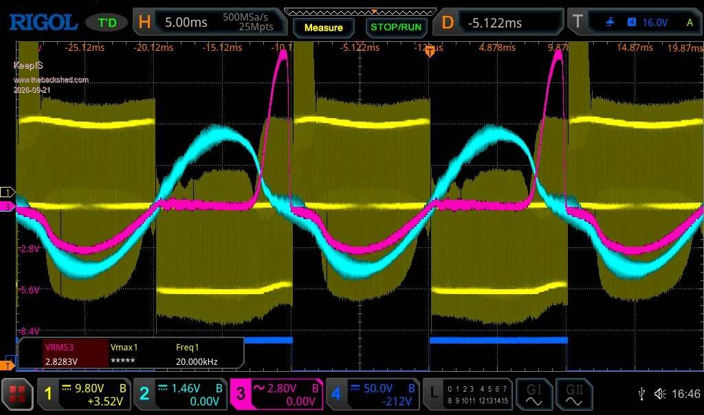 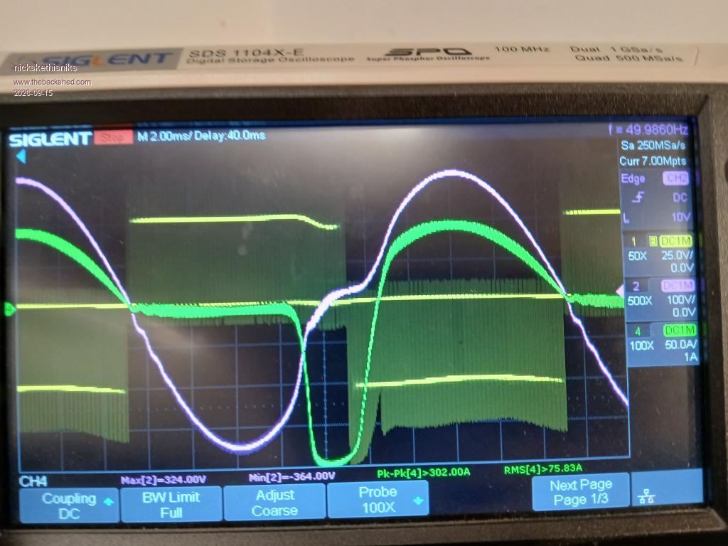 So, my conjecture is that reducing the unloaded half-cycle PWM drive will result in more balanced voltage magnitude for both half cycles and less of a kink (lower THD?) in the unloaded half-cycle voltage waveform. This may work for the flux walking problem with linear loads but I doubt it would be adequate for half-wave loads. I might be paranoid but the core saturation due to large (relative the the inverter capacity) half-wave (and more generally unbalanced) loads is more than a little voltage distortion. The stress from the huge magnetizing current pulses on the FET's and transformers is non-trivial and likely causing degradation over time. Edited 2026-10-05 03:30 by analog8484 |
||||||
Good to hear from you poida. For me, the half-wave loads are just one example of the issue with unbalanced loads. So, I am hoping for enhancements that can address more generalized unbalanced loads beyond just half-wave loads. I like the approach conceptually to include primary current sensing and effectively separate PWM scaling factors for the half cycles. It's definitely worth trying. However, it might be good to set our expectations. After looking at this issue for quite a while, I am coming to the conclusion that for large (relative to the inverter capacity) half-wave loads the inverter can reduce core saturation meaningfully in the unloaded half-cycle but not necessarily enough to avoid it to the extent of "no huge short current spikes due to saturation". The magnetizing current pulse peak may still be significantly higher than the load current peak. It appears to be an inherent limitation of the low frequency transformer for SPWM inverters because the there is a practical limit to how much the unloaded half cycle drive can be reduced and still maintain proper AC voltage output. In any case, I am all for enhancing the inverter as you proposed. Edited 2026-10-05 04:23 by analog8484 |
||||||
I think a differential current sensing setup would get us way better accuracy than subtracting ADC readings. If the turns ratio is, for example, 5:1, we send our primary current through in one direction, and send the secondary current through 5 times in the opposite direction. Balanced loads average zero direct current output from the sensor. Unbalanced loads will drive a comparator up or down accordingly. A slow control loop could then act on that single input. Edited 2026-10-05 09:57 by InPhase |
||||||
I am not sure if this fits here but we were talking about EV chargers on the previous thread before this thread started I have been using my wood splitter today, it is hydraulic and has a 2.2kw motor. Well I had a lot of trouble getting it to start this morning. I use a battery drill to spin the rotor up a bit then hit the start button. But this morning it didn't want to go, and then when it did the inverter kept going out on overload. I switched from my 8010 based 4kw inverter to my 3kw latronics inverter and it would not start the wood splitter either. After a while of the wood splitter cutting out every few minutes on the 8010 inverter I had an idea. I can change between inverters to back feed the GTI inverters, so I switched the load for the wood splitter to the 3kw Latronics inverter and left the GTI inverters backfeeding through the 8010 inverter. Well the wood splitter started much easier, and did not cut out at all while using it. So the problem was that the inverter did not like running a 2.2kw load and backfeeding at the same time. The wood splitter motor also sounded unhappy when the GTI inverters were helping to run it. With the GTI inverters running through the 8010 backfeeding and the Latronics 3kw running the wood splitter it was much quieter and did not cut out at all. Pete |
||||||
A DC current sensor with two primaries is certainly worth a try as it removes the need for two precision current sensors. To minimize the risk of blowing FETs during testing, instead of modifying reliable PWM code a temporary test setup previously mentioned would be safer. When the DC Amp-Turns required to cancel various levels of core flux imbalance have been determined firmware changes can be considered, with limits to ensure the feedback never pushes it too far. If the feedback method mentioned by InPhase for getting the difference between the primary and secondary Amp-Turns works out then suitable integration time to get the DC component will also need to be found. Just measuring the primary DC component isn't enough. When there is DC current in the secondary an equal number of DC Amp-Turns must flow in the primary to counteract it. Only the imbalance between primary and secondary DC Amp-Turns needs to be corrected. The net flux in the core (AC and DC) is the difference between the fluxes produced by both primary and secondary Amp-Turns, plus the magnetizing current. I hope this diagram better shows what I was trying to describe before. In that I left out all the series impedances as they are small compared to the load impedance (after factoring in the turns ratio) but have included them here for completeness. 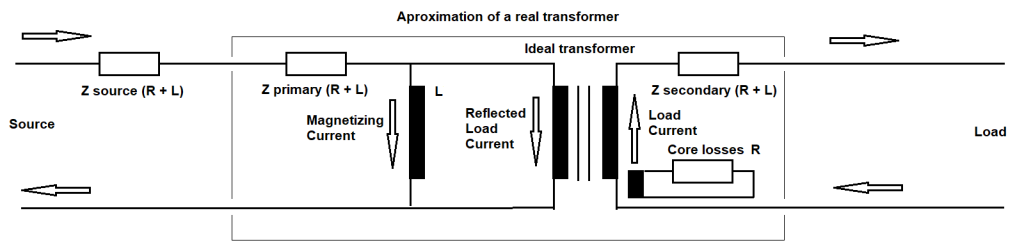 Edited 2026-10-05 16:58 by phil99 |
||||||
I like the new diagram much better, I think I am a more visual person. The idea of a current sensor with two windings equal to the turns ratio of the toroid sounds like a good plan. ie Toroid 8:1 then 1 turn on primary side 8T on secondary side. For a balanced load the magnetising current needs to be removed or ignored by the anti-saturation circuit. If an LEM or similar solid state sensor is used, by using the single sensor dual winding, I would expect the usual annoying drift and offset issues of solid state sensors would be largely ignored/cancelled as they are using a common sensor. However, wouldn't the control output from the anti-saturation circuit needs to apply the correction to the second half of the 180°, the un-loaded portion of the cycle, That is where the saturation occurs due to over drive? The loaded part of the cycle causes under magnetisation due to the impedance losses whilst the unloaded portion still has full magnetisation. Maybe the DC current source needs to be modulated by the 180° half sine to get better tracking and cancellation and a "linear" analog system could perhaps even work. The asymmetrical magnetisation is the cause of the resultant DC offset leading to saturation. There is a fair bit of testing and analysis required to find a working solution. Maybe a lookup table approach to apply the correct neutralising current at say 8 or 16 discrete steps, depending on the imbalance magnitude from the dual winding imbalance sensor is a suitable approach? One reason I also like from the proposed approach is that it does not require changes to the code for initial experimenting - the problem is not really with the code per se, its coming from the behaviour of the magnetics. Edited 2026-10-06 10:39 by wiseguy |
||||||
 |
The Back Shed's forum code is written, and hosted, in Australia. |