Posted: 10:33am 10 Jun 2018 Copy link to clipboard
matherp Guru
This function takes a trigger pulse on pin-15 (28-pin) or pin-42 (44-pin) MM2 and uses it to create an output pulse on a user-specified pin with a user-specified delay and of user-specified duration.
NB: The Cfunction can not be used at at the same time as IR input
In the example a pulse is created 10mSec after the trigger for 500uSsec
Once set up the pulse generation will operate in the background and create a pulse whenever is sees the trigger. The parameters for the generated pulse can be changed at any time by calling the function again.
The maximum pulse length is a function of the CPU speed and is defined by the equation:
maximum pulse length in seconds = (65536*8)/(CPU speed in Hz) CPU speed must be either 40MHz or 48MHz
The demo code should be self-explanatory. C-code is also attached for interest
' ' To use the test program connect pin 4 to pin 15 ' setpin 15,CIN pwm 1,60,0.5 pause 3000 print pin(15) oneshot 14,10000,500 timer=0 do loop while timer<10000 oneshot 14,5000,1500 timer=0 do loop while timer<10000 oneshot 0,0,0 end ' ' subroutine oneshot ' outputs a positive going pulse after a pre-determined period after a trigger pulse is received ' will continute to respond to each trigger pulse received until the output is turned off. ' The trigger pulse must be applied to pin 15 of a 28-pin Micromite which must be previously set up as a counting input
' ' This function takes as parameters the following ' ' pin number of the pin to output the pulse ' pause after trigger before the pulse in microseconds (maximum is 524288/CPU speed = 13.1mSec @ 40MHz ' duration of the pulse in microseconds (maximum is 524288/CPU speed = 13.1mSec @ 40MHz ' ' Use pin number =0 to turn off the output ' ' WARNING - the program has no error checking. Pulse durations greater than specified above will be rounded down modulus 524288/CPU speed
#define Version 100 //Version 1.00 #define _SUPPRESS_PLIB_WARNING // required for XC1.33 Later compiler versions will need PLIB to be installed #include <plib.h> // the pre Harmony peripheral libraries #include "../cfunctions.h" //#define MX470 #define magic 0 #define t1pin 1 #define t1port 2 #define t1count 3 #define t1dwell 4 #define t1duration 5 // void T1Int(void){ PR1=CFuncRam[t1duration]; *(volatile unsigned int *)CFuncRam[t1port]=CFuncRam[t1pin]; if(!(CFuncRam[t1count]--)){ mT1IntEnable(0); T1CON=0; } } void E2Int(void){ CFuncRam[t1count]=1; //used to hold count of cycles PR1=CFuncRam[t1dwell]; T1CON = 0x8010; // T5 on, prescaler as input mT1IntEnable(1); } __attribute__((noinline)) void getFPC(void *a, void *b, volatile unsigned int *c) { *c = (unsigned int) (__builtin_return_address (0) - (b -a)) ; }
void main(long long *pin, long long *dwell, long long *duration){ volatile unsigned int libAddr ; getFPC(NULL,&&getFPCLab,&libAddr) ; // warning can be ignored, stupid editor getFPCLab: { } int mydwell=*dwell, myduration=*duration, tickspersecond; tickspersecond=CurrentCpuSpeed/8; if(*pin==0){ mT1IntEnable(0); T1CON=0; CFuncInt2=NULL; CFuncT1=NULL; return; } mT1IntEnable(0); ExtCfg(*pin,EXT_DIG_OUT,0); CFuncRam[t1port]=(int)(volatile unsigned int *)GetPortAddr(*pin,LATINV); CFuncRam[t1pin]=1<<GetPinBit(*pin); PinSetBit(*pin, LATCLR); CFuncInt2=(unsigned int)&E2Int + libAddr; CFuncT1=(unsigned int)&T1Int + libAddr; CFuncRam[t1count]=1; //used to hold count of cycles CFuncRam[t1dwell] = (mydwell*(tickspersecond/1000000)); //wait time in ticks CFuncRam[t1duration]=(myduration*(tickspersecond/1000000)); PR1=CFuncRam[t1dwell]; T1CON = 0x8010; // T5 on, prescaler as input mT1SetIntPriority(1); // high priority mT1ClearIntFlag(); // clear interrupt flag }
Edited by matherp 2018-06-11
Posted: 12:12pm 10 Jun 2018 Copy link to clipboard
Zonker Guru
A big tip of the hat to you Matherp for investing your time to help everyone here on the forum..!! A very giving person you are fine Sir..!!
Posted: 01:21pm 10 Jun 2018 Copy link to clipboard
Chopperp Guru
Hi matherp
I concur with Zonker.
Took me a while to work it out, but I eventually got something going. About the first thing I found out was to use integers for the delay & width variables.
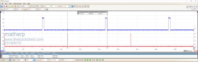
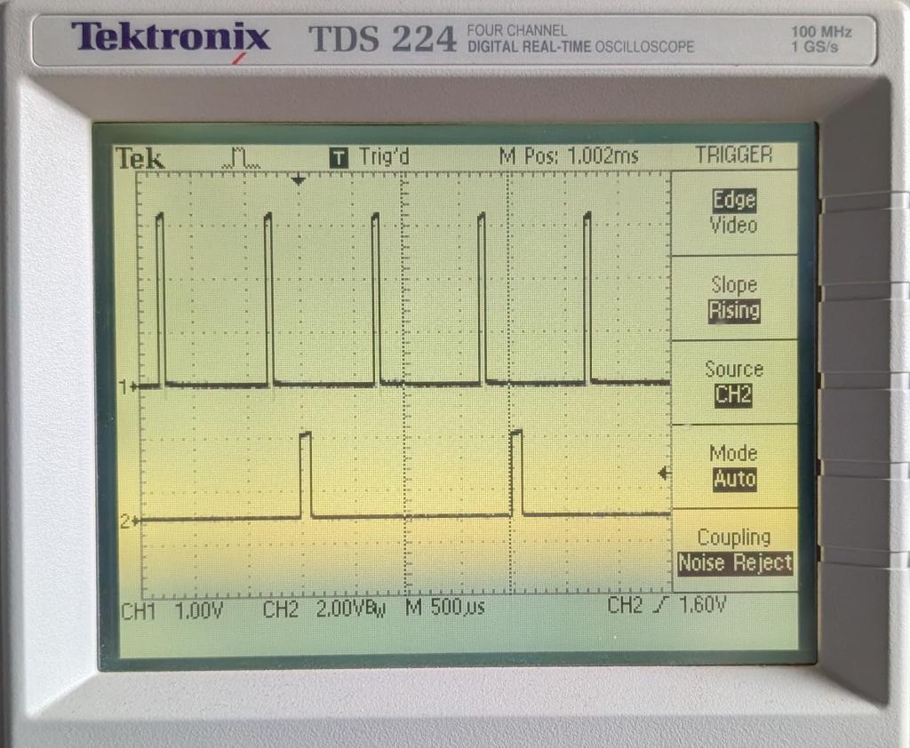
I have it going in a 1 sec loop monitoring a voltage for the width & triggering at 100Hz. (Rectified mains). However, every so often, it will miss a beat as shown by the snapshot below or the width varies slightly. (Delay 1000mS & width ~ 6700mS). It would need to run in a faster loop.
Did some more testing & my trigger signal probably needs improving. I reduced the level slightly from what photo shows & it is behaving much better. More testing needed on my part.
It does appear to have an occasional hiccup when running from the test signal. My test setup is a bit rough though.
This is certainly a huge step in the right direction. Very, very much appreciated.
option autorun on ' To use the test program connect pin 4 to pin 15 ' setpin 15,CIN setpin 7, ain
do delay% = max(1000, min(8000, pin(7) * 3000)) oneshot 14, 1000, delay% pause 1000 loop end
ChopperP
Posted: 02:58pm 10 Jun 2018 Copy link to clipboard
matherp Guru
Do you have delay and width backwards in your code or is this what you mean? The first parameter is the delay after the trigger and the second is the width of the pulse.
There may be some timing issues associated with changing the parameters while a pulse is running. I'll have a look at how this can be fixed
Posted: 05:27pm 10 Jun 2018 Copy link to clipboard
matherp Guru
This version waits if a pulse is active until it completes before applying the new parameters. I've tested it on the scope and can't see any evidence of faulty pulses.
Posted: 09:02pm 10 Jun 2018 Copy link to clipboard
Chopperp Guru
Hi matherp,
Yes, Delay should have been labeled Width. Still experimenting on how to best use it.
Will test the new version bit later on today & report back.
Thankyou very much..ChopperP
Posted: 12:51am 11 Jun 2018 Copy link to clipboard
Chopperp Guru
Fantastic!!!! Working perfectly as designed.
As you mentioned, there is no error correction. I found a too wide a pulse gave an inverted output. Limiting the width solved that problem.
I also experimented with some gating pulses. The idea worked on the breadboard. Yet to be tested in real life though which may take a week or two. QLD Courts reckons I need to do Jury Duty. I'd better go.
EDIT OOPS Just realised that my gated pulses aren't correct. Should be after the pulse end. Back to the drawing board.
option autorun on pwm 1, 10000, 50 'HF trigger pulses for the SCR, gated by PIN 14 setpin 15, CIN 'Trigger input setpin 7, ain 'Sample volts in. 0-3V3 setpin 23, inth, trigger 'PIN 23 connected to PIN 15
do width% = max(500, min(8750, pin(7) * 3000)) 'width limited from ~ 0.5mS to 8.75mS pause 8 'simulating doing other stuff loop
sub trigger oneshot 14, 1000, width% end sub
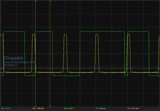
Trigger + Normal O/P
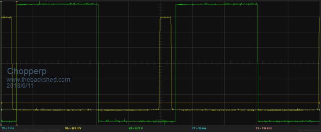
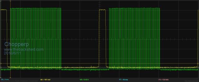
Trigger + Gated O/P
Edited by Chopperp 2018-06-12ChopperP
Posted: 10:59am 12 Jun 2018 Copy link to clipboard
Chopperp Guru
Hi matherp
It appears that if I stop the program below & then restart it, Oneshot does not restart.
OK if the MM is reset. Test signal on PIN 16 stops & starts OK.
option autorun on pwm 1, 10000, 50 'HF trigger pulses for the SCR, gated by PIN 14 setpin 15, CIN 'Trigger input setpin 7, ain 'Sample volts in. 0-3V3 width% = 8750 'initial Start oneshot 14, 900, width% pause 1000 setpin 23, inth, trigger 'PIN 23 connected to PIN 15 setpin 16, dout 'test point do width% = max(100, min(8750, pin(7) * 3000)) 'width limited from ~ 0.5mS to 8.5mS pause 8 'simulating doing other stuff loop
sub trigger oneshot 14, 900, width% pin(16) = not pin(16) 'test point end sub
ChopperP
Posted: 01:34pm 12 Jun 2018 Copy link to clipboard
matherp Guru
You probably need to call "oneshot 0,0,0" to reset it. Let me know if it worksEdited by matherp 2018-06-13
Posted: 02:16pm 12 Jun 2018 Copy link to clipboard
Chopperp Guru
Will try tomrrow ThanksChopperP
Posted: 09:24pm 12 Jun 2018 Copy link to clipboard
Chopperp Guru
Thanks matherp, that workedChopperP
Posted: 05:29am 27 Feb 2026 Copy link to clipboard
Mechanical Newbie
Hi matherp
New to this site - Geoff G kindly provided your Version 1 Oneshot module - which I loaded and it worked perfectly. However, I did note an issue with re-activating the command, while the previous oneshot was active.
(Minor) trap for young (old) players - your version 2 code lacked list the Csub oneshot first statement, and I missed this so the library came up with an error. Fixed that - and interestingly the code initially came up with a CPU Exception error - forgot to note the code, but restating it was all good - now pulse width changes seem to change seamlessly.
At one stage I did note the output pulse signal became inverted (instead of pulse high, it changed to pulse low). Noticed this on my oscilloscope - but so far have been unable to replicate this.
BTW - in the original C code, I noted the comment // MX470. Does this mean the code could run on an Exp-64? (I'm using an Exp-28).
Many thanks Mechancal
Posted: 07:55am 28 Feb 2026 Copy link to clipboard
Mechanical Newbie
Hi again, matherp
With prolonged testing, I have experienced several instances of pulse inversion - in one case when no further requests for change were made it began flipping between modes.
I wondered if the code had been configured to sense the initial pin status. Using pin 18 as the output, I had been setting PIN(18)=0 : SETPIN 18,DOUT early in my code. Tried pre-setting PIN(18) = 1, but this wasn't it (plus, I didn't want to do this, for project reasons).
Interestingly, setting PIN(1)=0 immediately after the oneshot call as a work-around seemed to help a little, but not solve the issue. FYI, I clamp the maximum pulsewidth to 9.7 msec, and have run successfully up to 9.9 or even 9.95 ms during testing. Was interested to see the maximum pulsewidth is lower for a faster CPU speed!
The problem is that when the inversion occurs the only way I can clear it is to recycle the power (CPU Restart doesn't achieve anything, not does ^C, run - which often causes the issue). I was interested to see that the pulse generation (and PWM) continues after ^C - I guess to be expected as the code runs in background. If I exit my code using ^C, then run, the issue doesn't fix itself - in fact, the output pulse stream often goes to a free-running square wave of about 26.2 ms (2x 13.1 ?) for up to a second or so. If I hit ^C, then enter PIN(18)=1, the pulse inversion sometimes corrects itself - but then goes back inverted on RUN. I am using PWM at 100Hz and 0.5% duty cycle to trigger the oneshot. CPU at 40MHz.
When the code is working normally, it is most impressive - very accurate, and stable pulses. Perfect for what I'm trying to do.
Any ideas please - best regards Mechanical
Posted: 08:37am 28 Feb 2026 Copy link to clipboard
phil99 Guru
It appears this has been seen before.
width% = max(100, min(8750, pin(7) * 3000)) 'width limited from ~ 0.5mS to 8.5mS
Stopping it.
Posted: 10:27am 28 Feb 2026 Copy link to clipboard
matherp Guru
I'd forgotten all about this and don't even have a development enviroment for the PIC chips anymore.
HOWEVER coming in PicoMite V6.02.01b7
Posted: 11:13am 28 Feb 2026 Copy link to clipboard
phil99 Guru
For the MM2 something like this might be worth a try, depending on the accuracy required. Trial and error may be needed to adjust the delay correction factor.
PIN(18)=0 : SETPIN 18,DOUT 'pulse output pin SETPIN 19, INTH, OneShot 'rising edge trigger input pin Dim Delay = 100-0.02 'subtract command processing time from desired delay (mS)
Sub OneShot Pause Delay Pulse 18, 10 '10mS pulse End Sub
Have been using a similar thing on a MM2 as a substitute for BITSTREAM. A packet of data is sent when an external trigger arrives. Data encoded in 5µS (1) and 11µS (0) low pulses. Works well, although for this application a few µS variation in the interval between pulses is tolerable.
Edit. If there is a possibility another trigger could arrive during the delay perhaps this may be better.
PIN(18)=0 : SETPIN 18,DOUT 'pulse output pin SETPIN 19, INTH, OneShot 'rising edge trigger input pin Dim Delay = 100-0.02 'subtract command processing time from desired delay (mS)
Sub OneShot Setpin 19, OFF 'disable interrupt, more delay correction will be needed for this Pause Delay Pulse 18, 10 '10mS pulse SETPIN 19, INTH, OneShot 'restore interrupt End Sub
Edited 2026-02-28 22:21 by phil99
Posted: 01:18pm 28 Feb 2026 Copy link to clipboard
Peter63 Senior Member
nice
Posted: 08:38am 01 Mar 2026 Copy link to clipboard
Mechanical Newbie
Wow - a lot of responses...
Unfortunately, the PULSE command is only accurate below 2.9ms, above that it is only very approximate, buy my need is for accuracy to 9.7ms - I have been trying matherp's oneshot C Module - which works with microsecond (not millisecond) inputs - is very accurate, and includes external triggering - ideal for my purposes. The maximum pulsewidth with CPU speed set at 40MHz is 13.1ms - I clamp to 9.7ms.
Hi matherp
If I use "PIN(18)=0 : SETPIN 18,DOUT : SETPIN 15, CIN : ONESHOT 0,0,0" at the start of my code, the output goes permanently HIGH - until I call oneshot again with the intended pulse width - but then I often get a long dummy shot before settling on the intended pulse width. It is important that I don't get random switching. But if ^C then RUN the output then goes low until the next oneshot call. Commenting out the "PIN(18)=0 : SETPIN 18,DOUT" causes the output to go tristate after "oneshot 0,0,0", then work properly when I next set my intended oneshot settings. Without the initial "oneshot 0,0,0" and DOUT the following settings don't work. So it's either "PIN(18)=0 : SETPIN 18,DOUT", or use "oneshot 0,0,0" - but not both. Using "oneshot 0,0,0" is necessary to stop the inverted signal - as otherwise I have to recycle the power to get out of that mode.
Where I set the pulse width, I found the following code helps a little:
IF msecs > 9.7 THEN msecs = 9.7 (have tested this up to 9.9ms, retriggering at 10ms) ONESHOT 18, 20, CINT(msecs*1000) PIN(18)=0
Whilst these different arrangements have reduced the incidents of pulse inversion, don't think the problem is yet "licked".
BTW I am triggering with PWM 1,100,50,50,0.5 (PWM 1C) - 100 Hz, 50 microsecs
Without sending changes, I once had the output pulse flick randomly but occasionally from normal to inverted, then later back again. But today I left the background running (after ^C out of my code) for a few hours - without seeing inversion.
Just for your interest - I am receiving 433MHz LIPD wireless signals from another device that decode to a variable used to calculate the required pulse width, which is then set. These signals are sent every time a light source is interrupted, either not at all, or once every 1 to 3600 seconds. The received ASCII characters are stored on interrupt to a circular buffer, just in case the uP gets a little behind things.
As a final comment - I loaded oneshot into the library - the very first time I ran oneshot, I got a CPU Exception error. I am wondering if the library could have been corrupted, and I should delete and re-install oneshot (or put it into the main code).
Best regards Mechanical (because I are one!)
Posted: 09:26am 01 Mar 2026 Copy link to clipboard
matherp Guru
Have you tried the code in the PicoMite? I'm going to add an optional dwell period after the output before the thing will re-trigger. I no longer have the MM2 code and can't update it so if you stick with that you will have to work round any limitations. The PicoMite code can be fixed if not perfect. Here is the result of my PicoMite version with the added quiescent period GP6 and GP9 connected.
setpin gp6,pwm pwm 3,1000,5 oneshot gp9,positive,gp2,300,100,1000 'Wait a positive going edge on GP9 then pause for 300uSec, then 100uSec pulse on GP2, then wait 1000uSec before allowing a re-trigger.
Edited 2026-03-01 19:50 by matherp
Posted: 09:57am 01 Mar 2026 Copy link to clipboard
phil99 Guru
If this is referring to the C source of ONESHOT, the first version of it is at the end of the first post in this thread.
Page 1 of 2
The Back Shed's forum code is written, and hosted, in Australia.