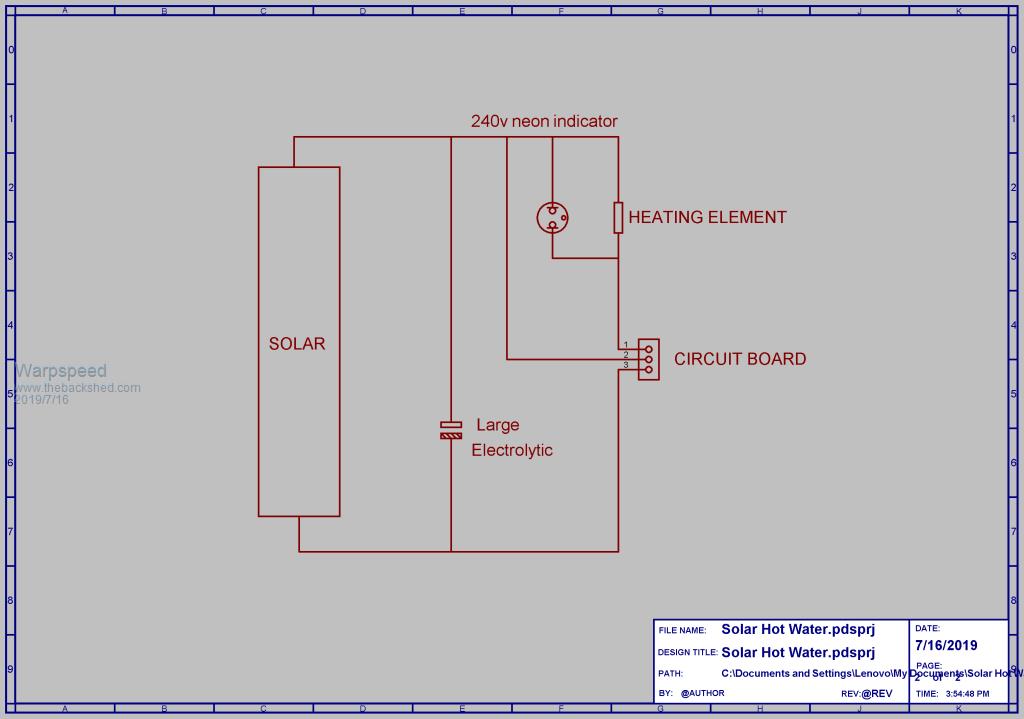
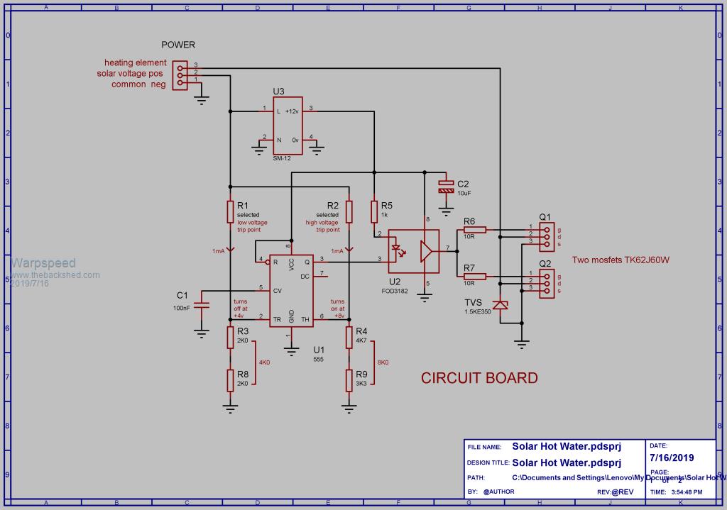
O/k first of all, here are the main wiring diagram and the circuit board schematic.

The number of solar panels may vary, but assuming a 220/240v heating element there may be typically eight 24v panels in series.
A large electrolytic will be required possibly around 4,700 uF 350 volts minimum, or at least something that can safely withstand the full no load solar panel voltage.
The circuit will cycle faster with a lower capacitance and more slowly with a higher capacitance. So the actual value is not that critical.
A 230v neon indicator will flash on briefly during each discharge part of the cycle to show that all is well.

The two resistors R1 and R2 should be one watt carbon resistors which are physically larger than the usual small metal film resistors, to ensure they both have a sufficiently safe voltage rating.
A small Chinese postage stamp sized 12v dc power supply provides power.
The voltage switching thresholds of the 555 will be 1/3 (4v) and 2/3 (8v) of the dc supply voltage.
There are two voltage dividers that set the switching thresholds, and the 555 will switch when the current flowing through R1 and R2 each crosses one milliamp.
This makes resistor selection much easier.
So the low threshold voltage when the heating element turns off will be four volts plus R1 value in K ohms.
The high threshold where the heating element turns back on will be eight volts plus the value of R2 in K ohms.
These voltage thresholds are not ultra critical so the nearest commonly available resistor value will work just fine.
Now for a hypothetical example.
Suppose the rating sticker on one of our solar panels says maximum power at 32 volts.
And we decide to set the heating element turn on upper voltage threshold to 36 volts, and we have eight panels in series.
The upper threshold would be 8 x 36v = 288 volts.
If we subtract 8v from that we get 280v, and theoretically a 280K resistor.
A 270K resistor will be close enough for R2.
For a lower voltage threshold where the heating element is turned off, we might decide 26v is about right.
Lower threshold would be 26v x 8 = 208 volts.
If we subtract 4v from that we get 204v and theoretically 204K resistor.
A 200K resistor would be closest value for R1.
The voltage will be ramping between something like 204v and 278 volts assuming everything is perfect.
Its swinging up and down over a 74 volt range, so a few volts error at either end is really nothing, because the power curve of our panels is flat and very broad.
The power drop off at each end might be something like 10%, and the average over that range could be in the region of 95% of what it is right at the very peak.
Cheers, Tony.