| Menu | JAQForum Ver 26.09 |
| Menu | JAQForum Ver 26.09 |
Forum Index : Electronics : Basic torroid bulk charger from gen 240v
Page 1 of 2   |
||||||
OK like the title said, the plan is to wind a torroid of 2-3Kw or so size to take in the 240v ac from a inverter generator, output will be rectified and I would assume it should be at the bulk charge voltage, in my case 57.6v for a flooded bank. Basically this will be intended as a last resort to charge the bank in case there wasn't sufficient solar. So no real smarts required to taper off current and go into float mode etc. Just a really simple way to get some capacity into a down battery. The normal charging methods will still be in place to look after proper charging, this is just intended to bulk charge in cloudy spell conditions. Last winter I scraped by and didn't need any supplement, but one more day of cloud would have changed that balance. So it pretty much just needs the correct winding ratio and then rectify the output. Why does that sound too simple? I must be missing something. Cheers Caveman Mark Off grid eastern Melb |
||||||
You are on to it Mark, grab a couple of high current schottky dual rectifiers like these STPS160H100TV to make a bridge rectifier. They have only 0.8v drop so are reasonably efficient. It always pays to have a plan "B", I would also add one of those set point voltage switches that are available on AliExpress to the output, and have it open the mains connection to the transformer primary via relay contact should the bank voltage get too high, as it might be difficult to get an exact voltage output from the rectifier. Cheers Mike |
||||||
Excellent idea Mark. I think it might also need to have a large choke between the rectifier and the battery to flatten out the huge current peaks, otherwise its going to be pretty tough on the generator. I may even have something here suitable for that. Cheers, Tony. |
||||||
inverter welder I use one of these, 3 more turns on the secondary side of the " transformer " and you have a variable current controlled 48v battery charger, that will happily do 3kw all day... Light weight and well built I think it works !! |
||||||
Thanks Mike and Tony. I have some spare big ferrite E cores if that's needed. Noneya, I have a similar welder, I tested the output plugs and there is no output, it only seems to work after the electrode has a strike, then it starts welding. Is there some trick to bypass that? Cheers Caveman Mark Off grid eastern Melb |
||||||
That is a far better idea. You might be able to get it "started" by placing a suitable resistor across the output? Don't really know, never messed with one of those myself. Cheers, Tony. |
||||||
Hey noneya, can you hook up a multimeter to the connections and get a reading with that unit you showed? If that's the case, I'll just get one of those, and keep my other one as a welder, I need one anyway. Cheers Caveman Mark Off grid eastern Melb |
||||||
Yes the output voltage is about 90v sort of like OC voltage on a panel, as soon as load hits it, it drops, but ive never had a problem with it... i just make sure its hooked to battery before turning on.. I know some have that " feature " but that one ( which is the same i have, and pretty sure the likes of oztules etc. ) doesn't have it.. I think it works !! |
||||||
Just looking, the " rossi " ones i have purchased for a friend and was well built too... and cheaper lol.. its actually quite surprising what you get for the price, oz reckons they weld quite well too..  Check specs in photos, most have about a 60v OC voltage, full current about 25v... why i suggested adding the extra turns, found you need to, to get the full range of current control, else its limited by voltage ( mine out of box was about 1200watt). Edited 2020-04-24 08:06 by noneyabussiness I think it works !! |
||||||
Just checked mine again and it has open circuit voltage!! WTF didn't before. Used another multimeter and nothing.... Grrr swapped probes and it works on that multi now. One set of probes in the bin then. Good news it shows 62v O/C, I'll hook it up to 48v battery later and see what it does. Then add turns if required. Cheers Caveman Mark Off grid eastern Melb |
||||||
This is the one The specs say 72v open circuit, but it's actually 62v. Anyway I hooked it up as is to the battery and it feeds in 1.9 Amps. So more turns are required. Opened it up and it looks like this. 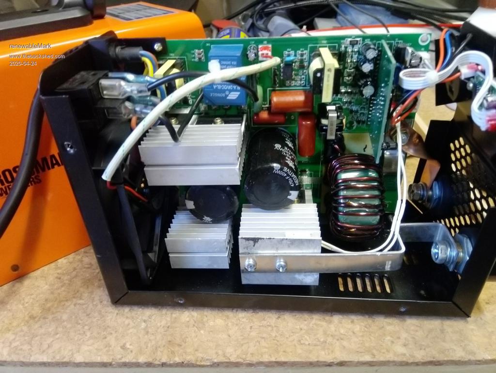 The coil looks to have two windings on it, one common that goes to the negative lead on the output. 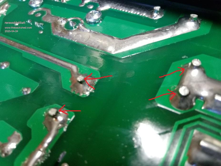 The other ends go to a small transformer about the size of a dice, and the other end goes to the drain of one of the IGBT's 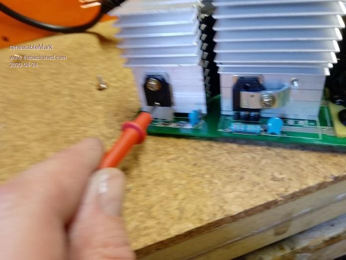 So is the idea to add windings on both? 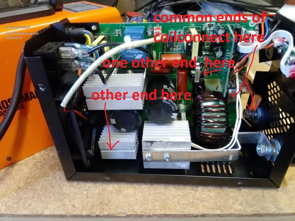 Edited 2020-04-24 16:17 by renewableMark Cheers Caveman Mark Off grid eastern Melb |
||||||
I'm trying to work out how many extra turns will be required for my unit. From your above post, did you mean out of the box your I-max one would feed 1200 watts into a 48v bank? If so, mine is 1.9 Amps, so around 100 watts out of the box. So my one will need more turns added than what you did. Cheers Caveman Mark Off grid eastern Melb |
||||||
Hi Mark. First time I've ever seen inside something like that, the "coil" I think is actually a transformer. It looks like it could have 3 windings. I think you should employ Poida or Warps skills to modify the first unit unless Noneya has that exact unit and can assist you. If it has 3 windings at least one will probably be the HV power drive (~ 350VDC), the other 2 could be a full wave rectifier for the output. You are probably correct to add 2 turns to 2 windings, but the winding going to the IGBT drain/collector may not be the right one to touch. Tread warily & good luck! If there are 2 tracks from windings going to devices on the larger heatsink with the strap on the topside going to the other output terminal they would probably be the windings to add turns to - I cant tell from the pictures. Edited 2020-04-24 19:42 by wiseguy If at first you dont succeed, I suggest you avoid sky diving.... Cheers Mike |
||||||
Off topic sorry.... Mark how many kilowatt hours does your house need from dark to sunup the following day - lets not include any air conditioners for the purposes of this estimation ? I received one of the Sirius super cap batteries today at a bargain price which I think is 3.6kWH, just wondering how far it might stretch. Yeah I know....I need to do a proper audit. I got it to do some more serious inverter testing but maybe after it could stretch through the night. Edited 2020-04-24 19:48 by wiseguy If at first you dont succeed, I suggest you avoid sky diving.... Cheers Mike |
||||||
I really cannot help here, as I no nothing about these types of welder. I would need to actually have one in front of me so I could try to figure out what it all does, and then try a few things. It may not need to have any of the main windings physically changed, perhaps just the feedback or the system that controls the output voltage. It depends how far short the voltage is. Definitely has possibilities though, but it might also be fairly easy to kill it if you did the wrong thing. Cheers, Tony. |
||||||
Oh come on Tony wheres your sense of adveture lol. I looked again at the PCB pictures its just an overgrown PC Power supply with a half bridge drive ? The two red arrows pointing to the left are actually the drive winding I reckon, the two thick wires you can just see at the top side of the same picture I reckon are the other ends of the common (high current output) winding. I believe there is no voltage feedback only current feedback from the shunt so you need to add sufficient turns until the current limit is working and that it pushes reasonable current as the Batt voltage climb to full. A mans gotta know his limitations ......... Edited 2020-04-24 20:12 by wiseguy If at first you dont succeed, I suggest you avoid sky diving.... Cheers Mike |
||||||
You could be right Mike, as there is only a single knob that controls current. There may be more to this though. That winding on the toroid does not look like capable of 200 amps to me. Cheers, Tony. |
||||||
But Tony they are metric Chinese amps not imperial ones. That is why it has a overtemperature shutdown - they know it cant sustain 200Amps they have a 5 or 10% duty cycle but I'm sure they would claim higher. Go on help Mark I know you want to.... Have a good weekend - BTW how many hours through the dark hours of night will 3.6kWH get you ?If at first you dont succeed, I suggest you avoid sky diving.... Cheers Mike |
||||||
yes, that was my thought too. Wiseguy, overnight draw isn't much at all, the idea for an extra charger is to supplement the solar array when there has been a cloudy spell lasting for days. Cheers Caveman Mark Off grid eastern Melb |
||||||
BTW this thing welds like an 80 amp unit does, no way it can provide 200 amps. Totally fine for little jobs @ $100 it's still a good little unit. Cheers Caveman Mark Off grid eastern Melb |
||||||
| Page 1 of 2 |
||||||
 |
The Back Shed's forum code is written, and hosted, in Australia. |