| Menu | JAQForum Ver 19.10.27 |
| Menu | JAQForum Ver 19.10.27 |
Forum Index : Microcontroller and PC projects : Trying to ID a connector....
| Page 1 of 2 |
||||||
Hi all.  I am trying to ID a connector from inside an LCD projector. Both of these connectors are the same, and both of them connect to 12v cooling fans. Can anyone help me ID what they are, so I can order some replacements? This projector, although fabulous in terms of image etc, has ZERO cool-down when you turn it off. This has resulted in moderate LCD burn-in as the projector is NOT cooled down when you turn it off, so the residual heat then slow-bakes the LCD, which is not good.  I have another one coming, but I want to mod it, so that I can include/force my own cool-down period, when you turn the thing off, thus preventing the burn-in on the new one. 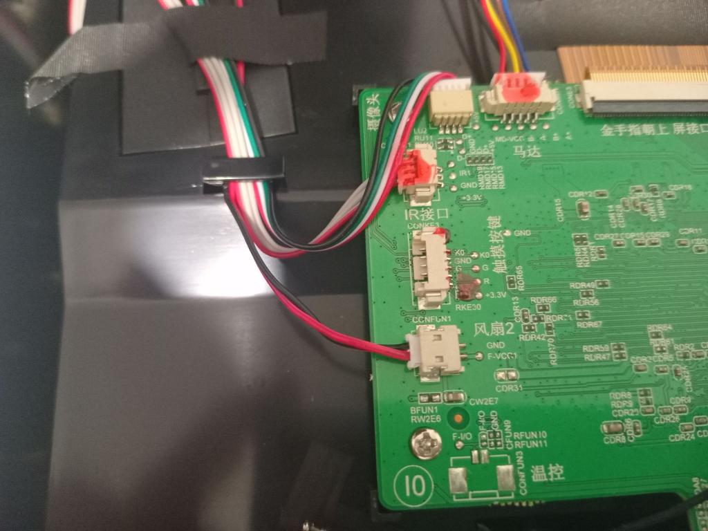 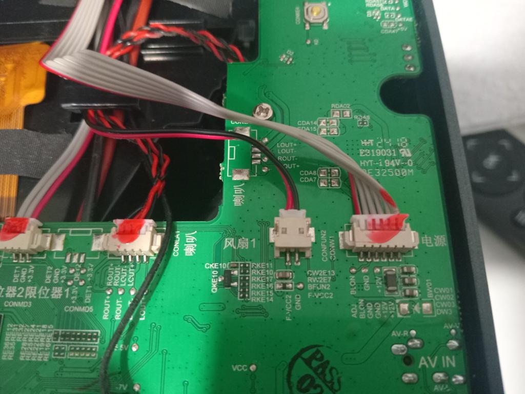 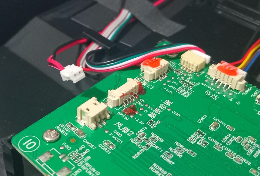 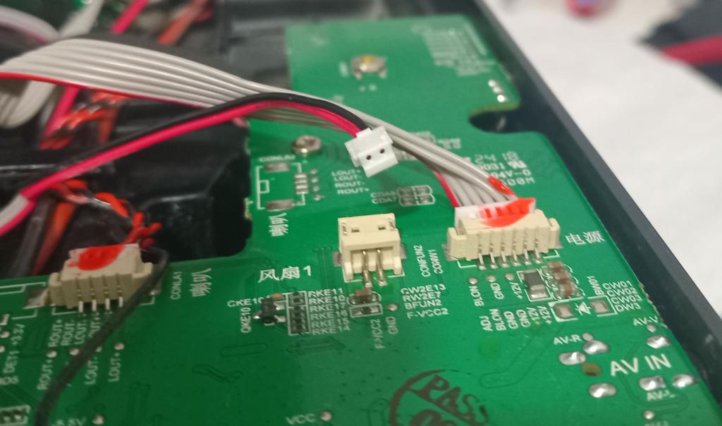 Smoke makes things work. When the smoke gets out, it stops! |
||||||
JST XH ? |
||||||
They definitely look like JST of some sort. There are variations in pin pitch, make sure you get the right one. I'm guessing that the fans simply run while the power is on? If so, I'd simply cut the fan wires and connect them to a board that handles sequencing them: Switch board on start fans start projector Switch board off stop projector delay stop fans Take power control to the projector off the human, leave it to the board. |
||||||
Excellent, thanks. @ Mick - my thoughts exactly. Yes, those fans start when the projector starts, and simply stop when you turn off the projector. The projector is excellent, but cos there is no cool-down period, the poor LCD gets slow-baked every time you turn it off.  Bad design, considering how good the image is when the thing is running, and how simply it WOULD have been, to include a simple cool-down timer in the design.  I plan to pretty much implement exactly the process you indicate, but I thought it would be nice and neat, if I designed a board to do the fans, using the same connectors. I guess that is not strictly ESSENTIAL. |
||||||
If the fans are 12V I see use for a 555 here. :) |
||||||
They are 12v fans. Both fans are connected together, even though on different sockets and different parts of the main PCB. I used diode-test on my multimeter to confirm they are both in parallel, so I plan to use one of the sockets as the trigger for some kind of cool-down timer, with the fans then being powered from the main 12v to the mainboard. Basically, when powered on, nothing happens, but when you turn the projector OFF, and both of the fans power down, I am hoping to use that vanishing 12v on one of those sockets, to trigger a timer to keep the fans going for another 30 seconds or so, then they switch off too. I'd probably use an opto-coupler where the fans used to be, to isolate the projector mainboard, from my exta bit, and that also allows me to have a clean trigger signal via the opto, for whatever timer I end up using. That's the plan. |
||||||
Current idea - 555 "One-Shot" circuit:  Replace LED1 with an N-Ch MOSFET as a low-side switch, fans in parallel in the high-side to 12v. S1 replaced with PC123 NPN opto. When the projector is turned on, the opto will trigger the 555, and hold the 555 in the "Ready" state - the fans will spin-up. When you turn the projector OFF, the opto will drop out, and the 555 will start running at that point, keeping the fans running. When the time is up, the 555 will switch off, turning off the fans. Does anyone see any thing obviously wrong with that idea? I will probably still breadboard it to check this will work, but then I will get some simple PCB's made. Edited 2025-06-15 14:57 by Grogster |
||||||
A CMOS 555 will save 10mA when idle, if you are after minimum standby power. |
||||||
Is there power you can use for your circuit once turned off? |
||||||
YES. The PSU in the projector, has one main high-current output for the LED light, and a smaller output to the mainboard, which is 12v. That 12v is on the mainboard all the time the projector has power, so that it can come out of, and go back into, standby mode. |
||||||
ok.. if this is a standby power I would check if it has enough current to drive the fans. Without scheme it is a risk simply to try, it might hurt some regulator |
||||||
Oh, it does. This 12v comes direct from the PSU, and is used to drive EVERYTHING on the mainboard - fans included. 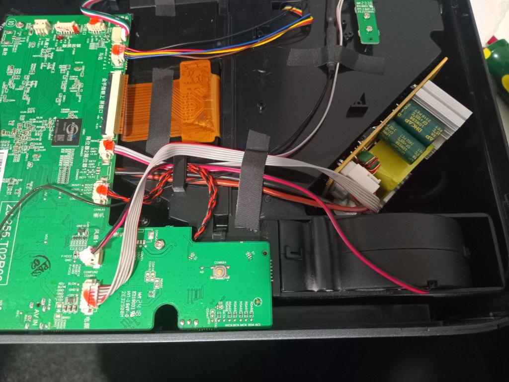 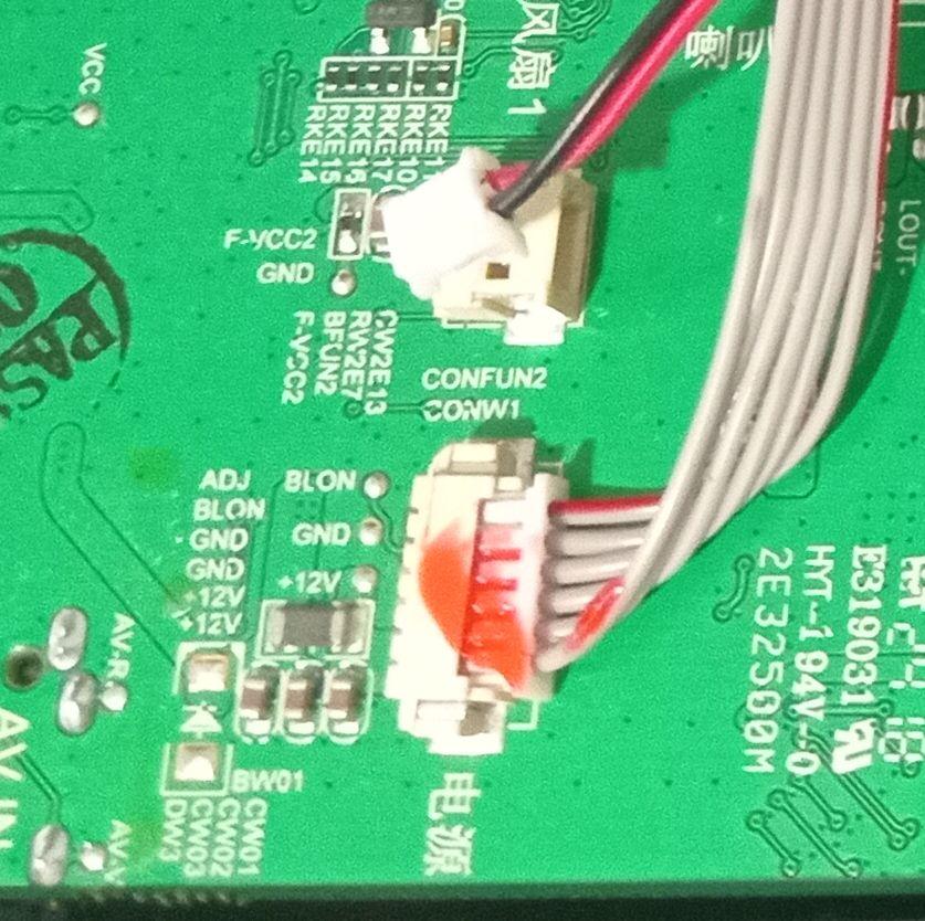 Now, this is my free-hand drawing of the schematic I am planning to breadboard in the next few days. If anyone sees anything obviously wrong here, please do post a comment.  I have a whole bag of 14N05 N-Ch MOSFET's, so that is why I am using these to drive the fans. The maximum gate-source voltage is +/- 10v though, so with a 12v mainboard voltage, I am using the two 10k's to make sure the gate of the 14N05 never sees more then 6v worse-case, which is still well within the 10v maximum. |
||||||
It's a good idea to have a pull-down on the gate anyway. It never does any harm. :) If your signal from the fan socket is correct, i.e. the fans are switched to +12V and share a common ground, then you could replace the opto with a NPN transistor and base resistor - or a small mosfet like a 2N7000. R2 can probably be 10K or so. Just a thought... Have you checked to see which side of the fans is switched? You might be able to simply link the switched side to the appropriate supply rail to force them on. No need to rewire them to another board at all. Of course, doing that might power up the rest of the device. :) |
||||||
NPN vs Opto - good point.  Fans to supply rail - yes, that probably WOULD work, but the problem is that the fans would then run 24/7 - even if the projector was "Off". That is no good, as it is a projector in my bedroom, and I could not stand the fan noise all night long. |
||||||
No, what I meant was to switch the fans to the supply rail using a mosfet or even a relay. It won't work if the fans are on a supply shared with the rest of the board though, I suppose, but it might if they are currently switched by something on the board. :) |
||||||
OK, so I will then proceed along the lines of the 555 circuit, and perhaps just drop the opto, and have an NPN on the input. Would you be happy with that arrangement? |
||||||
How much current do the fans draw? If the main 12V is off they will need to be powered by the standby 12V. Can it supply what the fans need. |
||||||
About 350mA with both of them running. I measured it today. With the projector "Off", there is a healthy 12v on the mainboard. I don't THINK it will be an issue. When the projector is "Off", the 12v supply is still active, it's just that the projector is in a powered-down state. As we have TWO 12v wires and TWO ground wires from the main PSU, even when the projector is off, it can obviously happily supply at LEAST a couple of amps, to get the mainboard running, when it comes out of standby. In other words, there IS no "Standby" 12v supply, it is simply there all the time. Powering off the projector, simply puts it to sleep, for want of a better term, but the 12v rail from the PSU is still there and ready to be used. I will build a prototype on a breadboard in the next few days and run some tests. |
||||||
A lot of stuff is like that now. Switching supplies can drop to very low standby current when the load is disconnected or turned off. There is still quiescent current, but it can be low. It sounds like your proposed system will work fine. :) |
||||||
How about just adding a supper cap circuit so fans fast turn on but have a slower off. I am using a few 5vdc 4.0F to do something like this but keeping a relay active a bit longer controlling a 6" ball valve. Power at the valve is stable but the controller can lose power and when that happens they want the valve to close all the way. Quazee137 |
||||||
| Page 1 of 2 |
||||||
| The Back Shed's forum code is written, and hosted, in Australia. |


