Posted: 08:06am 04 Jul 2025 Copy link to clipboard
Bryan1 Guru
Well first Peter I do think we need to come up with a name for this new board and big daddy does come to mind as it will be a beast in any project one takes on.
My board from Grogster has finally arrived and in 3 hours and counting it will be in my hands as my daughter picked it up this morning and she is working and gotta say she is only 17 and has been made a manager
Well with that out of the way a circuit board will need to be made where opto isolated outputs for the DM556 Stepper boards which will accept a 5 volt input. Now Harm did make me a file where it proved a 2040 could drive a axis so with big daddy it should be a breeze.
Now the question as some pins on this board can handle 5 volts will they output 5 volts ?
So my idea is to use a 2040 with a 3.5" touch screen with a ILI9488 so it can be mounted on the CNC to provide live updates from big daddy and be there for jog functions etc where the 2040 can report back on any movement.
Now big daddy will be setup with a VGA screen (well no HDMI screens here) and a USB hub setup for keyboard and mouse.
Essentially 4 pins for each axis will be needed for enable, direction, step and count as for each step which can be calibrated has to be counted for accuracy as no encoders are used.
More ideas will come to mind and remember this black duck will be learning from the get go on the coding side as the grey matter comes into play also with other projects on the go aswell. Also has it has been awhile my sprint layout skills will need a touch up to suit JLCPCB.
Regards Bryan
Posted: 08:50am 04 Jul 2025 Copy link to clipboard
Volhout Guru
Hi Bryan,
The 2350B on the big board will output 3.3V, and (there are some that argue) should receive 3.3V at it's inputs. When your 556 stepper motor driver requires 5V you will need a level shifter. That can be a 74HCTxx gate (i.e. 74HCT04 is an inverter).. anything that can translate 3.3V to 5V and can drive a line (not one of those FET level shifters).
If you want opto coupler isolation, maybe you could look at TPS2745/TPS2345 opto couplers. These are fast, digital, can be powered from 5V to output 5V, and only require 2mA LED current (can be driven from a RP2350 pin directly with 470 ohm or 1k series resistance).
For input PhenixRising uses differential inputs (since his encoders are differential output). But in minimum you need a 5V->3.3V resitor divider and protection diodes...
Volhout
Volhout
Posted: 09:28am 04 Jul 2025 Copy link to clipboard
Bryan1 Guru
Thanks for that Harm I can add that to the component list as I do think opto isolation will be needed as it has been done since day one of stepper motor drives.
I do have a heap of those buck converter chips that output 5 volts and ones that output 3V3 so they can be used and I just need to work out the foot print for sprint layout.
Now for getting boards made at at JLCPCB is a total new thing for me I will need a hand with with my sprint layout design to suit that.
This is going to be a huge learning curve for me as I put my mind to this as it has been close to a decade since I was involved with this stuff.
Now as you are a guru with this PIO stuff how would it go counting steps as that will be needed.
As the 556 can accept 24 volts and that is the voltage I'm using for the CNC I'm thinking it may be best to drive it from 12 volts where the datasheet says a 2.2K resistor should be put inline (the grey matter) is coming back.
Well I do have my splitting water project down pat so I can have a hydrogen torch so I can move onto this project.
Edit: Well finally got hands on my board now the first thing to do is set the pot and program it with the latest firmware. Edited 2025-07-04 20:47 by Bryan1
Posted: 10:36am 04 Jul 2025 Copy link to clipboard
PhenixRising Guru
I use optocouplers for 24V inputs from machine sensors.
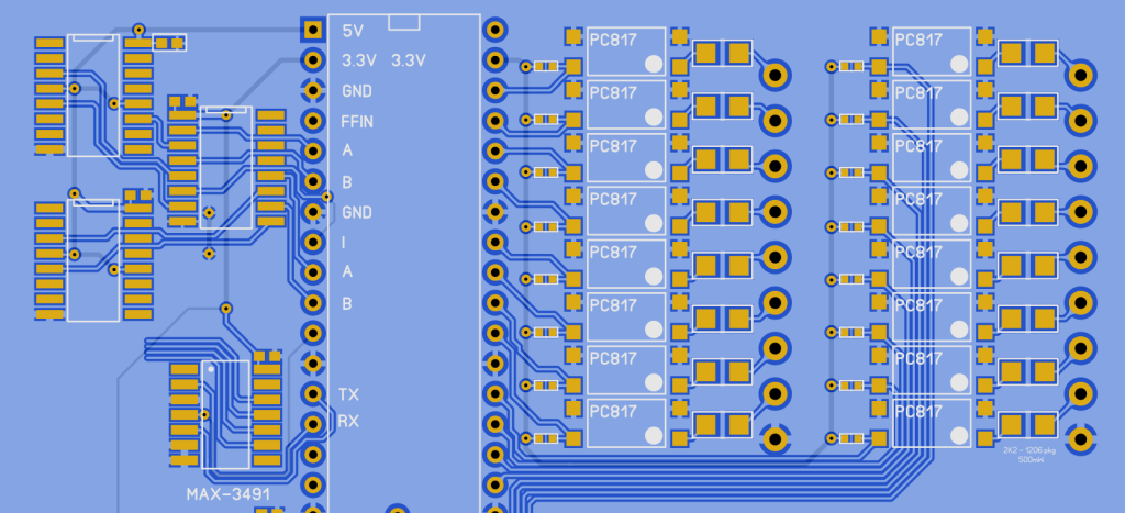
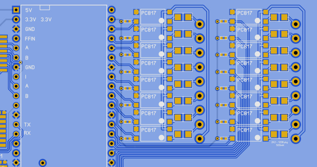
The unlabeled devices (top left) are for two encoder inputs (I prefer two encoders per axis). They are MC3486 differential line receivers although they can be configured to handle single-ended encoders. The device between those and the RP2350 DIL is a CD4050 for 5V to 3.3V.
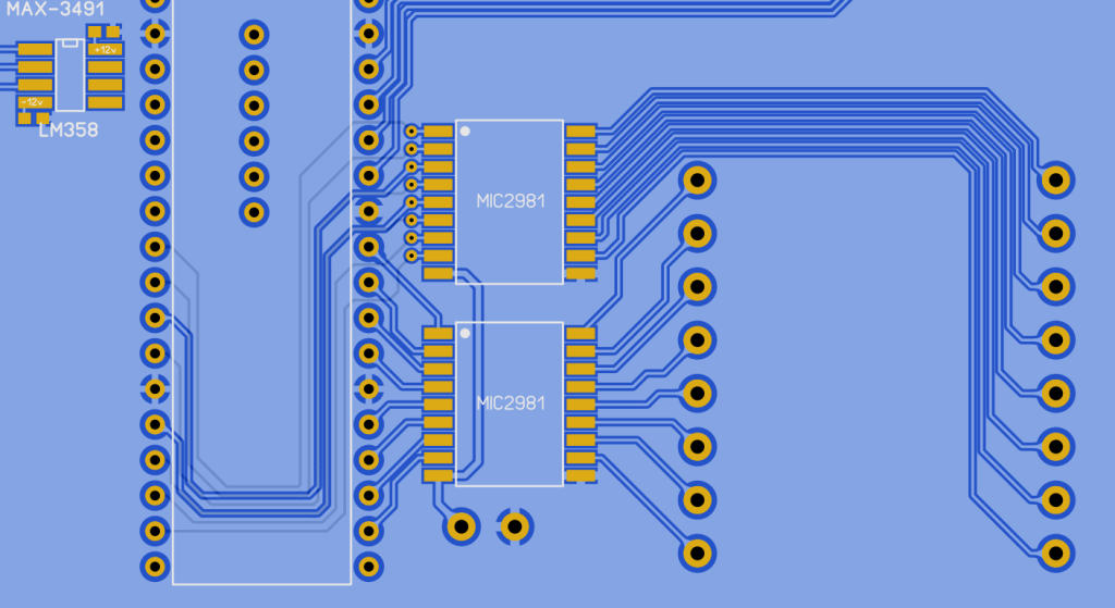
The MIC2981 is used for outputs. The datasheet states that it can be used for stepper-drives. It can handle a decent amount of current although I only use it to give me up to ~30mA per output with negligible load on the RP2350. The two terminals under the MIC2981s are for external supply (up to 50V?). For me, this is typically 24V although some machines can be 5V or 12V
Bryan, I am happy to share my SL6 files although Matherp has inspired me to go to the dark side (SMD)
My days are filled with running around the country, keeping production lines running and so I don't make the rapid progress that our resident wizards do but I hope to get some done, this weekend. Edited 2025-07-04 20:39 by PhenixRising
Posted: 10:44am 04 Jul 2025 Copy link to clipboard
PhenixRising Guru
Harm already gave us step/direction
'step/dir_decoder_pico_PIO_version 4
'program options do_assemble=0 'either assemble the code, or brute force program use_test_signal=1 'internally generate test signal
'step pulse generation for testing if use_test_signal then stp_init 'init GPIO pins settick 10,do_step '10ms = 100Hz step frequency cntr = 0 'step counter direction = 0 '0 = count up, 1 = count down else setpin gp0,pio1 'the STEP signal setpin gp1,pio1 'the DIRECTION signal end if
'Generic defines f= 63e6 '63 MHz PIO frequency pio clear 1 dim dat%(4) 'array to store FIFO data
' PIO code -------------------------------------------------------------------
if do_assemble then 'assemble
'header and start of the PIO code pio assemble 1,".program test" pio assemble 1,".line 0"
'wait for step pulse pio assemble 1,"wait 0,pin,0" 'wait for GP0 to become 0 pio assemble 1,"wait 1,pin,0" 'wait for GP0 to become 1 = rising edge STEP pulse pio assemble 1,"JMP pin, plus1" 'jump according state GP1 pin
'The plus and minus routines, X is the actual 32 bit position counter pio assemble 1,"minus1:" 'label:jump here to decrement X pio assemble 1,"JMP X--, push_out" 'decrement X pio assemble 1,"JMP push_out" 'regardless X value go to push_out pio assemble 1,"plus1:" 'label to increment X pio assemble 1,"mov X, !X" 'invert X pio assemble 1,"JMP X--, next1" 'decrement x pio assemble 1,"next1:" 'label:regardless X value come here pio assemble 1,"mov X, !X" 'invert back
'send the most recent position to FIFO pio assemble 1,"push_out:" 'label pio assemble 1,"mov ISR, X" 'move X to ISR pio assemble 1,"push" 'push ISR into FIFO, not blocked
'jump to start of PIO program pio assemble 1,"JMP 0" 'jump to beginning
pio assemble 1,".end program" '50900RC4 and newerr 'pio assemble 1,".end program list" 'needed for 50900RC3
else 'brute force program the same code
dim p%(7)=(&h4800c520a02020,&ha0290047a0290008,&h8000a0c1,0,0,0,0,0) pio program 1,p%()
end if
'configure PIO 1 statemachine 0 (PIO 1 is free on PicoMiteVGA) p0=pio(pinctrl 0,0,0,gp0) 'gp0 is lowest IN pin (gp0,gp1) e0=pio(execctrl gp1,0,31) 'GP1=dir, wrap and wrap target s0=pio(shiftctrl 0,0,0,0,0,0) 'shift IN direction is left (the 5'th '0')
'initialize PIO 1 state machine 0 pio init machine 1,0,f,p0,e0,s0,0) 'init machine @ start loop
'start the quadrature decoder PIO 1 statemachine 0 pio start 1,0
'get the data from the fifo pio read 1,0,5,dat%() 'read whole fifo posi%=dat%(4) 'last data in fifo if posi%>2147483647 then inc posi%,-4294967296 '2'th complement print posi% 'show position
'just some pause pause 100 'any delay needed
'reset position (PIO X register) under control of keyboard if a$="r" then 'press r to zero position pio execute 1,0,&hA023 '= assembly "mov X, null" (zero the X register) a$="" end if
'set defined position in register X under control of the keyboard if a$="s" then input "desired count ";cnt% cnt%=cnt% and &hffffffff pio write 1,0,1,cnt% 'write the count cnt% in the fifo pio execute 1,0,&h8080 '= assemble "pull" (moves FIFO to OSR register) PIO execute 1,0,&hA027 '= assemble "mov X, OSR" moves the OSR value to X a$="" end if
loop while a$="" 'exit when any key not r
end
'test code in MMBasic that drives GP0 and GP1 according sub stp_init setpin gp0,dout : pin(gp0)=0 'step pin setpin gp1,dout : pin(gp1)=0 'dir pin end sub
sub do_step 'this rountine counts 1000 steps up, then down, etc... inc cntr,1 'new step pulse gp0,0.1 '1 ms step pulse if cntr>=1000 then cntr = 0 direction = 1 - direction pin(gp1) = direction end if end sub
Posted: 11:10am 04 Jul 2025 Copy link to clipboard
Bryan1 Guru
Thanks for the code mate but with this new chip GP0 isn't there as from what I've learned it reserved for the PSRAM chip.
But this code is great for testing using a 2040 which I'll do tomorrow to test each axis.
Now as I build this CNC close to 20 years ago there is no reason with you guy's we can get it going again as the last time it worked XP hung and my circuit design was ruined and with end of 32 bit that was the end of mach 3 with XP Edited 2025-07-04 21:16 by Bryan1
Posted: 11:26am 04 Jul 2025 Copy link to clipboard
Volhout Guru
Hi Bryan,
When you have optocouplers at the input, you can also disconnect the LED cathode from your ground plane, and connect it directly to the ground of the system driving the input. As it is now, the optocoupler shares input and output ground. It does not isolate.
Do you have the 64 pin footprint correct? Maybe the photo is misguiding my eyes, but it feels a bit narrow.
When you plan to use the MIC2981 to drive stepper pulse and direction, you may want to add pull-down resistors from the outputs. The MIB2981 can essentially only pull high. Not pull low. The MIC2981 is a complement to the ULN2803 (that can only pull low, not high).
Volhout Edited 2025-07-04 21:32 by Volhout
Posted: 11:37am 04 Jul 2025 Copy link to clipboard
matherp Guru
The spacing between rows is 1". I tried to make it 0.9" to be the same as the 68000 processor but couldn't fit the tracks at that spacing
Posted: 11:47am 04 Jul 2025 Copy link to clipboard
PhenixRising Guru
Not Bryan, but
Hey thanks, Harm
Optocouplers: In fact. What I actually intend to use is the AC-type optocouplers. Yeah I'd better do it now or I'll never do it.
You are absolutely correct (great observation) re: width. Here's where I assumed it was the same as the RPi Pico and didn't measure or check Pete's gerbers.
I toyed with the idea of a pull-down on the MIC2981 but I have thoroughly tested these things with all kinds of loads and haven't seen the need. I will look at it
Posted: 11:51am 04 Jul 2025 Copy link to clipboard
Mixtel90 Guru
I wonder if that's my fault? I think I might have done a 0.9" footprint for SL6....
Posted: 11:58am 04 Jul 2025 Copy link to clipboard
Bryan1 Guru
Well for this black duck done enough today and got food for thought and I'm sure more posts will follow.
As far as what pins I use for each axis can be decided tomorrow as I do think that count pin is needed to count the steps.
Posted: 12:04pm 04 Jul 2025 Copy link to clipboard
Mixtel90 Guru
Very red-faced. :( Here's the fixed version! Pico2-64.zip
Posted: 04:18pm 04 Jul 2025 Copy link to clipboard
PhenixRising Guru
Thanks Mick
I'd already spaced mine out but I loaded yours anyway, superimposed it and it snapped right into place. What is it about SL6 that makes it so enjoyable. When I get to work on this stuff, sleep becomes a darned nuisance
Posted: 04:54pm 04 Jul 2025 Copy link to clipboard
PhenixRising Guru
Corrected DIL spacing and isolated optocouplers.
Posted: 05:52pm 04 Jul 2025 Copy link to clipboard
Mixtel90 Guru
I find SL6 relaxing. A set of little "how do I connect that to that?" puzzles. Mind you, it's something that's necessary even if you use a proper PCB package with an autorouter.
Posted: 06:30pm 04 Jul 2025 Copy link to clipboard
PhenixRising Guru
I WANT ONE
Posted: 10:57pm 04 Jul 2025 Copy link to clipboard
vegipete Guru
How often do opto-couplers let out the magic smoke? I prefer to have mine socketed so they can be replaced. Maybe that's unnecessary.
Posted: 04:39am 05 Jul 2025 Copy link to clipboard
Bryan1 Guru
Maybe I'm missing something here, first I set the board to 1.2 volts then programmed 2350VGAUSB in and win10 doesn't show any signs of seeing the board. So I just put the standard 2350 file on and got a message saying it was setting up the pico.
Not in teraterm when I have the VGAUSB loaded it can't see the com port and the device manager doesn't even show the com port for the pico. Also tried in MMEdit with no luck but when the standard file is loaded it all works.
Posted: 04:54am 05 Jul 2025 Copy link to clipboard
phil99 Guru
That is correct, the USB socket is now in "Host" mode to connect to a USB keyboard or hub. Serial console is moved to GP8, GP9 so you need a USB to TTL serial adapter co connect to a PC. See latest manual p32 "USB Interface"
If you don't have one you can use an Arduino Uno or Nano with the reset pin tied to ground. That will allow the CH340 USB/TTL chip to use the Tx and Rx pins. Though I think the Tx and Rx labels are then reversed. If it doesn't work one way try the other. There are series resistors on the Arduino so getting it wrong wont do any harm. Also connect ⏚ to ⏚ Edited 2025-07-05 15:00 by phil99
Posted: 05:24am 05 Jul 2025 Copy link to clipboard
Bryan1 Guru
Hi Phill thanks for the quick reply mate Now from back in the old days I do have a microbridge so would that one work ?
Page 1 of 2
The Back Shed's forum code is written, and hosted, in Australia.


 as my daughter picked it up this morning and she is working and gotta say she is only 17 and has been made a manager