| Menu | JAQForum Ver 19.10.27 |
| Menu | JAQForum Ver 19.10.27 |
Forum Index : Microcontroller and PC projects : 5in SSD1936 + PGA2350B = A fun sort of a design. :)
| Page 1 of 2 |
||||||
This is a design that I started ages ago but never got anywhere with it. The tracks just wouldn't work out. A few days ago I realized that the answer is to put all the components between the PCB and the display and mount the display on 15mm spacers. The back of the PCB has nothing mounted on it unless you add an optional expansion connector. 16-bit parallel display, of course. I had enough GPIO pins to play with. :) It's still at the design stage so nothing is fixed yet. 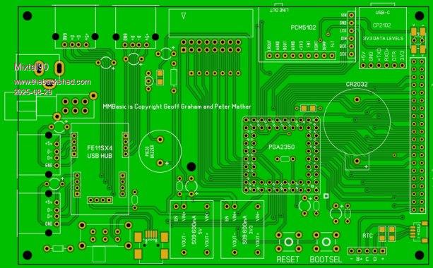 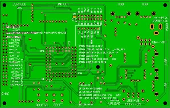 EDIT: Incidentally, just in case anyone is wondering at my choice of mini USB and the PGA2350B, it's because I already have them. :) Additionally, soldering a USBC socket to a PCB is something of a challenge and only for masochists! The on-board LED can be either a 3mm LED connected as a Heartbeat indicator or a WS chip lifted off a piece of strip, in which case it's useless for Heartbeat but you can have pretty colours. :) Edited 2025-08-29 03:59 by Mixtel90 |
||||||
Mick, I have successfully soldered down to 0.4mm by hand but not had any experience with ball grid - do you flow solder in from the back? Doug. |
||||||
You use regular headers. Can be a bit of a struggle to pull out if needed. |
||||||
It's not a ball grid, Doug. The PGA2350 is a module from Pimorini. It comes without any headers soldered on. I used the "snap off" turned pin headers. The 2-row ones don't just snap off, by the way, they are a bit of a pig! To use them on a PCB plug the male and female headers together, drop them into the board, put the module onto them, solder a pin on each, turn it over, solder a pin on each on the bottom with some pressure on. That gets everything aligned. Now you can solder them properly. Once they are soldered in and correctly aligned they aren't too bad to unplug. It takes a lot of pressure to plug in so many pins though. Last time I put the pcb on the floor, put the module onto it carefully then pressed it in with my foot! Everything still worked. :) Soldering BGA is best done on a hot plate. Put the solder paste on, put the board on the hot plate, align the chip and switch the hot plate on. Let it cool before disturbing it. It's also the safest way to get the things off as even hot air puts too much thermal stress on some components. |
||||||
Hello Mixtel, this design looks really nice! It has everything to be a full featured self contained computer. Very useful. |
||||||
It's still progressing: Optional separate series resistors on GP40-GP47 GP25 now available on rear expansion connector - it can be disconnected from the LED stuff with a solder blob link Choice of different piezo sounders Optional "true" power switch link, might be useful for battery applications Optional LM4040 VREF added (but it had to be SMD to fit it in!) Added a "Standby" LED off the back contact of the power switch Quite a few track changes, some just because it was prettier. :) I'm sorting out the circuit diagram at the moment. A couple of mistakes fixed. :) It's sort of a cross between a stand-alone boot to BASIC computer and a controller with a built-in touch display. My idea is that once assembled you wouldn't need to take it to bits too often. The rear expansion connector could take I2C, RS485, multi-drop COM, HC12 or Bluetooth - or just left off. The RTC doesn't need its supplied battery - the CR2032 will keep it running for years. It's a good use for an old module, although I'd probably take the battery off a new one and solder the module in solid. |
||||||
On holiday so not looking at the backshed much. If you made 15 I/O available in a block of 5 and an block of 10 then you could connect my Palm Pico keyboard. Also needs one extra output for the caps-lock LED. I could make the pins selection flexible and then it would be fully supported by MMBasic. 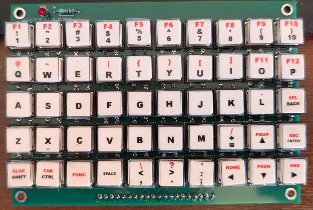 |
||||||
I could only do that by sacrificing all the GPIO and the console. Is that a fair swap? TBH I'd prefer a wireless USB keyboard personally, but others may feel differently. Nice little keyboard though! Or, how about converting your keyboard to some sort of serial, using a RP2040-Zero? |
||||||
A rather big set of changes today: Rotating the PGA2350 through 45 degrees to reduce most trace lengths on the board and neaten it. I rather wish I'd thought of that earlier. :) The LM4040 can now be either SOT-23 or TO92. There is now space and fixing holes for a 23mm piezo sounder. A diode across the piezo pads allows an external 5V/6V relay to be added if anyone wanted to. Well, the space was available. :) |
||||||
Hello Mixtel, nice to hear, that you further develop this project! If you are willing to release the gerber's once you are finished my plan is, to mill and build a prototype. I think this should be done as the trace length of rd,ws,rs needs to be tested to have an error free picture. I experienced problems with full standard PicoMite colours like R,G,B but a photo with RGB888 with the same setup looks good because only colours set to 255 cause these problems. On the other side I found, that once the electrical conditions are met, it runs very solid. Maybe it would be an idea, to implement the "CS combined" circuit to free one more GP and to have display's reset pin permanently high and free another GP. Maybe with a jumper. I have with your setup 17 free GP's The idea with Peter's keyboard is great and on top yours to have a 2040 being the keyboard driver which converts to PS/2 is even nicer and you have another project..to develop the firmware :) maybe a XL version in future? I think it's worth mentioning, that I think that any size of ssd1963 displays with this interface type can be driven with your board. |
||||||
After some playing about today it now has a fixing position (2 if you leave off one USB) to mount the 4.3" version of the display. I've also added a micro SD socket with a CS link to select either/or. This can be useful if the unit is panel-mounted. I'm not going to mess with the GPIO now. TBH I don't think it's worth it. I'd much rather have 8 ADC ports and GP1 available than have the ability to add Peter's keyboard. That could be a completely different project. This design should work fine with USB keyboards, mice and game controllers. GP31 and GP25 can now be disconnected by links and used for other purposes if required. They are only operating the piezo and LED. There's not a lot that can be done with those trace lengths, they'll either work or they won't. :) Using 16 pins for the data lines restricts what you can do, particularly when GP0 and GP1 aren't available. 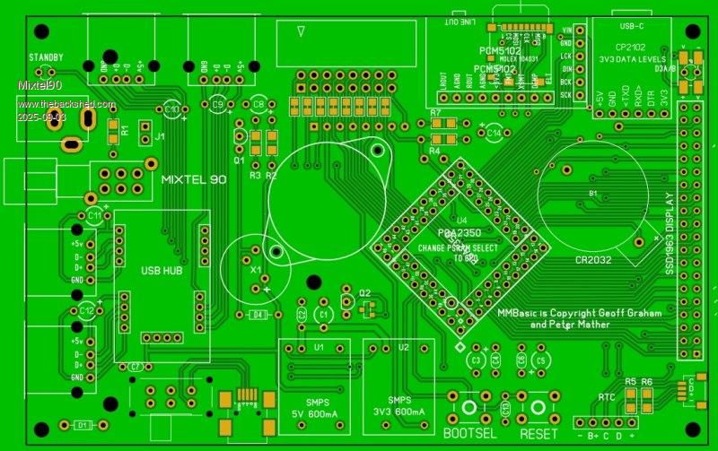 |
||||||
Much work later... I think this is almost it now. * A lot of trace optimization has gone on (you won't believe how much!) * I'm not using the audio socket on the I2S module now. That means that pulling on the lead isn't going to endanger the module connections even though it is still plugged in. * The expansion socket and the GPIO connector can have their VCC pin set to 3V3 or 5V independently (that's in addition to a 3V3 pin). * The GP25 output is now more versatile. * More decoupling caps have sprung up, together with wider traces on some major current paths. * The power supply system has changed a lot, sharing the 3V3 load over two circuits (the backlight can draw a lot of current). and more... I now have a circuit diagram for it too, and most of the manual. This morning I was contemplating adding a small relay that could be used instead of a sounder, but I'm not sure. No matter what I use it will be the wrong one for somebody so perhaps that's better remote if someone wants it. I also considered a ESP32 D1 Mini but it's a bit too cramped. One would fit on an expansion board though if anyone needed it. COM1 is available on there. 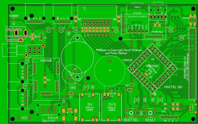 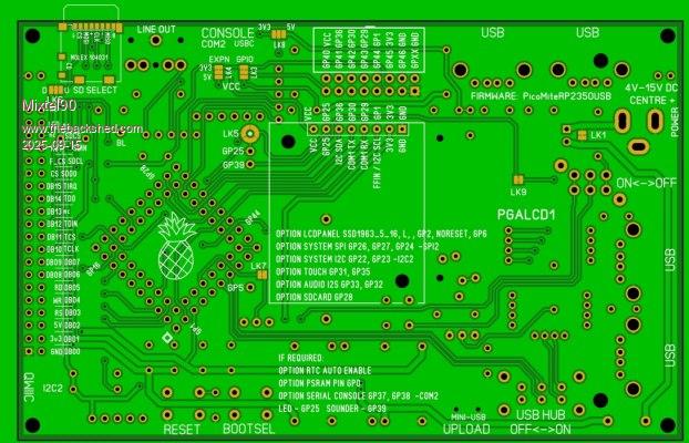 |
||||||
Hello Mixtel, looks excellent! My 7" with 100% brightness plus PGA plus Hub takes about 650mA current, so may be considering the 3A converters is an idea. Devices attached to the Hub is also a point. Changing the SDcard is something that I need to do quite often. I think the standard size is better to handle and more robust. But that's no moaning, your design and the PCB looks really nice! Regards |
||||||
This is designed around the 5" display, which draws a maximum of about 520mA from the 3V3 rail and doesn't use the 5V rail at all. I don't know the requirements of any other displays in the series so I've not attempted to set the board up for them. In particular, any larger displays will have no support so you would need to sort something out mechanically as well as electrically. :) The trace widths to the 3V3 and 5V pins of the display connector are only officially rated to 800mA. Any more than that and you will need to solder wires on. I can't make them much wider and can't double up on the other side as there are crossing traces there. I have no info on 3A converters so I can't help there. I just happen to have some S09 modules. :) If there's space I can look at it. I've found some but they have no EN input so you'd be asking that low current switch to switch the full DC load. Not great. Oh, and they won't fit the current layout either. :) . Edited 2025-09-16 00:59 by Mixtel90 |
||||||
This will fit on a 7" as well, I'm pretty sure. My SSD1963 only needs 5V and the 3V3 is done by a AMS1117 AFAIK and don't need to be supplied but there is 3V3_in at the display. As the 5" design seems to be the same I thought that it would also apply to it..but don't know Attached devices are definitely an issue, a mouse can draw more than 100mA and a PS4 controller I think even more when charging. It's up to you, my comments were meant to be constructive! example, there are many different types out there.. Edited 2025-09-16 02:14 by dddns |
||||||
The switch used can handle a maximum of 500mA per pole. With two in parallel you can probably expect about 700mA as one pole *will* operate before the other whether it's supposed to or not! That's into a pure resistive load too. I certainly wouldn't want to risk them at any more than that if I wanted them to be reliable. If the board is run from a battery that drops below 5V the combined current into the converters could be well over an amp (these things are usually pretty inefficient below and around boost mode). That's why I want an Enable input on the converters, it's no load. The board will let you use an external switch, but it's awkward and it won't go on the PCB. The USB hub is just that, a USB-A hub. As such the total current available from all four connectors simultaneously can't exceed the maximum available from a single USB port i.e. 250mA (which it would normally be plugged into as an unpowered hub). I doubt if most people will hit that, but it is definitely possible. The GPIO port probably won't have a lot of load. I've not measured the current drawn by the PGA2350 as that will vary anyway. At the moment I have about 600mA to share between them. |
||||||
This board in the way it's done is from my point of view ideal to have a "OTG" mini usb-c power connector. I would rely on that and recommend a 5V/2A power supply as minimum and leave out all 5V regulation. Only some capacitors and the issue is gone.. |
||||||
I considered that at the beginning. I eventually decided to go for nominal 12V operation from a vehicle battery. It would also be fine from a couple of 18650s if they had undervoltage protection or even 6V or 7V of dry cells. It *should* also work from 5V (there is an issue with the EN input of the S09). Yes, the problem goes away if you make it 5V only but you still need a converter or regulator for a 5" display as they don't use the 5V pin and the PGA2350 can't source enough 3V3. Then there's the issue of people using cheap SMPS plugs and getting a 70V or so tingle off the USB sockets because of the EMI cap. I'm not a great fan unless they are feeding an earthed system. :( I'll think... :) |
||||||
I've thought.... Coming in with a USBC "decoy trigger" module set to 5V. That allows connection to any of the "fast chargers", which will provide 5V at up to 5A. After that is a 555 in single-button bistable mode. That gives me a power button. The Discharge pin drives a parallel pair of P-channel MOSFETs in the 5V rail via a N-channel MOSFET (which inverts the signal) to provide the switched 5V. (Two because I have a lot of them). Because of the inversion the system powers up in the "off" state. A brief press of the button switches it on, a second press switches it off. High speed repeated pressing is ignored. Switched 5V feeds a 3V3 S09 and the PGA2350. The S09 is only feeding the display, but it is doing it with much less heat dissipation than a AM1117. I've had the 555 / MOSFETs circuit running in simulation and it's very good. No GPIO pins needed so fully compatible with just about any Pico software. Now to see how it can be done... :) |
||||||
Mick IMHO the widely available 5" SSD1963 is the worst SSD1963 variant. The display is dull and has a poor viewing angle, it requires more 3.3V than many boards can supply and at 800x480 the text can be too small to be useful as a console device. Both the 7" display which powers the backlight with 5V and the 4.3" display are much better. My new Palm Pico will use a 5" SSD1963 display but it is the one from BuyDisplay with an IPS screen and 5V backlight power. In addition I will be running it by default in a pixel doubled mode (400x240). It uses a different pinout so would not be compatible with your board which is a pity as I think it would give you a much better result. |
||||||
| Page 1 of 2 |
||||||
| The Back Shed's forum code is written, and hosted, in Australia. |
