| Menu | JAQForum Ver 19.10.27 |
| Menu | JAQForum Ver 19.10.27 |
Forum Index : Microcontroller and PC projects : High speed pulse trains
| Page 1 of 2 |
||||||
I thought I saw a post recently about sending High speed pulse trains. I couldn't find anything about it in the manual (maybe poor search foo). What is available? PicoMite, Armmite F4, SensorKits, MMBasic Hardware, Games, etc. on FOTS |
||||||
Assuming you want more flexibility than PWM there is Bitstream that works down to 1µS intervals, in increments of 1µS. Faster than that would require PIO I expect. |
||||||
BITSTREAM--thank you. Knowing what to search for makes such a difference. |
||||||
It can often simplify things using Array Set x, stream$() 'x = most common interval in µS, stream$() = Bitstream array to set the base timing, then your program can loop through the array changing the elements as required. Eg. in "Run Length" and "Pulse Position" encoding the intervals between bits are all the same so that would be "x" then you replace every second element with the bit duration. A For loop with Step 2 works nicely. Just make sure you get the starting polarity correct or the data will be inverted. Links to examples for IR Remotes and Keypads (scroll to 74HC595 version) on FotS. Edited 2026-03-06 10:21 by phil99 |
||||||
But, ah, the problem for me is that bitstream is blocking. Too much going on for blocking to be allowed. Not now, but when/if I get to it, PIO seems to be the way. |
||||||
G'day Lizby, Depending on the type of pulsetrain you require, PLAY LOAD SOUND might offer a way of saving the pulsetrain in an array and "playing" it in the background. Hope this helps. Regards, Lyle. |
||||||
If it's a high speed asynchronous serial string that needs accurate timing and must be non-blocking then you are stuck. MMBasic always processes interrupts after each statement so you can't write it in MMBasic as that will screw up the timing. BITSTREAM is blocking to get the accuracy. PWM will give you a hardware generated signal so that isn't blocking. I agree, a PIO looks like the only way - and only if it's a fixed sequence that will fit in its memory. Otherwise changing the data via a pipe and/or interrupts will probably mess things up a bit. |
||||||
lizby, what is the requirement? Perhaps I can do somethging... |
||||||
@lizby, There is a thread on high speed data send from picomite using PIO where they drive LED displays. The PIO outputs data from a circular buffer filled with data from MMbasic. So it could repeat endless, and an update of the buffer starts to send out the new data. But more info on your application could help. Do you know that Peter has a "buffered" driver for ILI9341 displays ? That also outputs high speed data using the second ARM core. Set up a "fake SPI display", write dummy data to it and it will be send out. ---bad idea--- it converts from RGB121 to RGB565. Volhout Edited 2026-03-06 20:34 by Volhout |
||||||
This is down the line, relating to making "Vibe Virtual Model Railroading" (posting today) less virtual, with the ability to send DCC controls. In talking with Gemini, it said you would need to send continuous repeating bit streams to keep engines rolling. For right now it's just a thought exercise--it's likely to be some time before I tested (and I have no actual model railroad gear). Gemini did suggest some test equipment. I understand that it could work with PIO (which is Greek to me, but I know help is available here). |
||||||
|
||||||
"DCC_details" Thank you for that. "Digital Decoders must remain in digital mode and not convert to using any alternate power signal so long as the time between Packet Start Bits is less than or equal to 30 milliseconds in duration" The 30 millisecond requirement is why in a busy program a blocking DEVICE BITSTREAM command wouldn't work. |
||||||
Much of the time the DCC packets are the same as the preceding packets so the Bitstream work could be farmed out to another Pico. It would just keep repeating the same bitstream(s) every 20mS or so until new data arrives from the controller Pico or CMM2. Serial coms is buffered so should not be affected by bitstream blocking. If you envision more complexity than that can keep up with, the slave could be loaded with a variety of acceleration / deceleration sequences in the form of sets of bitstream arrays. One set for each engine (read the set in reverse for deceleration). The slave would then need far less new data. Similar to the way Phenix controls multiple servos at high speed. However, by the time you need this Peter may have added the DCC protocol to the firmware. |
||||||
Yes, I had thought of that, and it would be a good solution. On the other hand, if DEVICE BITSTREAM could have an additional parameter saying if non-zero repeat this stream in the background after pausing this non-zero ms until a new stream was commanded, that would be ideal. |
||||||
Silicon Chip have articles on DCC this year, Jan, Feb, Mar. The last one is a DCC booster that could serve as a slave. It receives commands from the master over serial. Depending on the track layout you may need a couple of these for different sections. Loops and point sets can create polarity reversals that must be dealt with to prevent shorts as engines pass through. Even though it is an AC system polarity matters. Logic 1 = 58µS high and low, Logic 0 = 100µS high and low so not really high speed data. The average is around 6kHz. 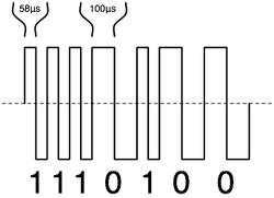 Edited 2026-03-07 21:15 by phil99 |
||||||
Any hope for this? The bitstream would continue sending in the background until a new DEVICE BITSTREAM command was executed. |
||||||
I have only just seen and need to hit the road so I have no idea about what we need to achieve but the first thing I thought of was Pete's new stepper driver(????) |
||||||
G'day Lizby, As mentioned in a couple of other posts, a second Pico receiving serial commands on a COM port (buffered) and using PULSETRAIN to generate the DCC waveform is probably a smart solution. As posted earlier, it is possible to overload PLAY LOAD SOUND to output pulse trains, this is however very "Heath Robinson" so no gaurantees... This was discovered by accident as usual.  Normally, play sound outputs a 44khz 50% duty square wave, PLAY LOAD SOUND modulates this with an array of values, these are 0-4095 (12bit) packed as 16bit words in an integer. If these 16bit values exceed 2fff the 44khz modulation is stopped and stays high. We now have a way of modulating a 44khz carrier with an array in the background, a little closer to what we need but the wrong frequency / repeat rate. So 4096 samples at 44khz = 93mS, too slow for DCC but if we use Play sound 1,b,u,4 we get a repitition rate of 23mS, pretty close to what we need. Some initial testing shows if a DCC 1 is set as &HFFFF &H0000 and a DCC 0 is &HFFFF &HFFFF &H0000 &H0000 we get pulse trains of 44khz carrier of approx the correct 58us / 116us length for DCC 1/0. We have 1024 values so thats 512 x DCC 1's or 256 x DCC 0's. A 555 timer connected to the output as a re-triggerable monostable set to approx 10us will invert and turn the 44khz into DCC pulses (Untested) Once again this is outside the normal use of this command. If time allows in the next few days (weeks?) I'll break out the DSO and test further, assuming we don't see it in the firmware at some point. Regards, Lyle. |
||||||
I wondered about PLAY LOAD SOUND too but the manual doesn't say whether it runs in the background or is blocking. Another thing to test. Unlike BITSTREAM it can endlessly loop the data until you change the data, which is what Lizby needs. An RC filter with a diode across the resistor might also work. The first carrier half cycle will rapidly charge the capacitor. During the next half cycle it will discharge a little slower through the resistor. As long as it is still just above the 1->0 threshold when the next half cycle starts the carrier will be removed. I used this in a 74HC595 one pin driver and could reliably determine when the data packets have ended and also distinguish between 1µS and 3µS data pulses. |
||||||
Phil, Sending: this sounds like a simple PIO program (similar to generating the 2 tone siren signal in the PIO training). The bytes are constituted to a 32 bit word, and pushed into fifo. From there the PIO takes care of sending out. MMBasic has to calculate the XOR of address byte and command byte to a checksum byte. It becomes more complicated when you also want to receive. Then you need a second pio statemachine to decode, triggered from the first to decode the bits. -or- you adapt to first statemachine to always decode (as if each command contains received information) but ignore on MMBasic side the response (dummy) on commands that do not require a response. As a basis you can use this...(type the PIO code in into the MMBasic Assembler, that should work). DCC RP2040 PIO on Github Volhout P.S. The final implementation could run from a ring buffer, as to always flood the railway with data, and achieve fast recovery for locomotives that have communication misses due to sparking. P.P.S. The 1 line controlled HC595 may not work reliable in a noisy environment like a model railway. Depending motor coil inductance, glitches of any length can be generated while the locomotives run. Edited 2026-03-20 19:05 by Volhout |
||||||
| Page 1 of 2 |
||||||
| The Back Shed's forum code is written, and hosted, in Australia. |
