
| Menu | JAQForum Ver 26.09 |
| Menu | JAQForum Ver 26.09 |
Forum Index : Microcontroller and PC projects : Playing with Tinkercad for box design
Page 1 of 2   |
||||||
I thought I'd have a go as I now have a mini 3D printer. Absolute max size 120mm x 120mm x 120mm. The one shown here is 118x114x30 when fully assembled and will just take a full 100x100 pcb. 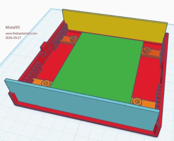 PCB supports are not moulded in and are printed separately so you have a free choice of where the fixings are. Little vertical supports on the sides will probably be enough to hold them in place, or there's always glue. :) The supports can also hold vertical PCBs or separators to keep the mains stuff away from the low voltage stuff. Due to the maximum bed size of the printer and the fact that I want a 100mm wide PCB screw case fixings aren't great (I tried it) so I'm trying a clip (which I'm working on). Note that the top and bottom of the case are identical. The front and rear panels keep them aligned and the clips hold the top on. The slots for the panels are 2mm wide so work nicely with PCB material. I need to be very patient with this little printer. It's old and slow (like me). :) Test pieces 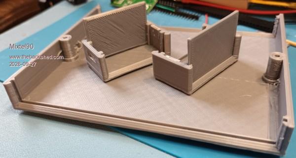 The little case hadn't enough "give" for the clips and they broke off. PLA is quite stiff. |
||||||
Very nice Mick. Designing new cases is a very rewarding experience. I look forward to seeing your end results. |
||||||
How long did it take to print, Mick? This 50mm x 50mm to 37mm round water diverter connector I had AI design for me took 2+ hours to print at the local library (costing me $2CDN). 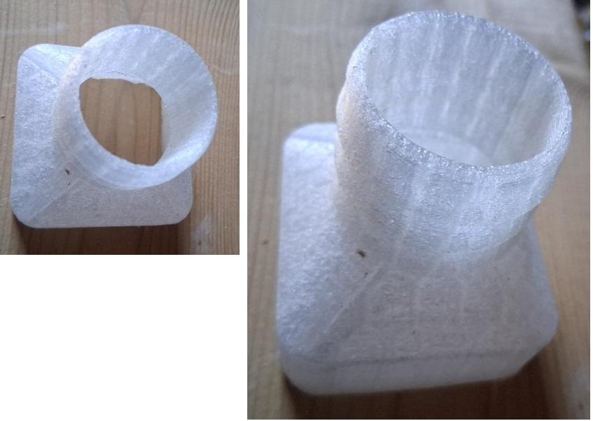 Your base looks like it might take 4 hours (not that that matters to me--I could drop it off or maybe even just email them a file). I could use a box that comfortably takes a 100mm x 100mm pcb. I'm not yet sure of the height. This is the Aliex box you recommended (very nice), but I'll need something bigger: 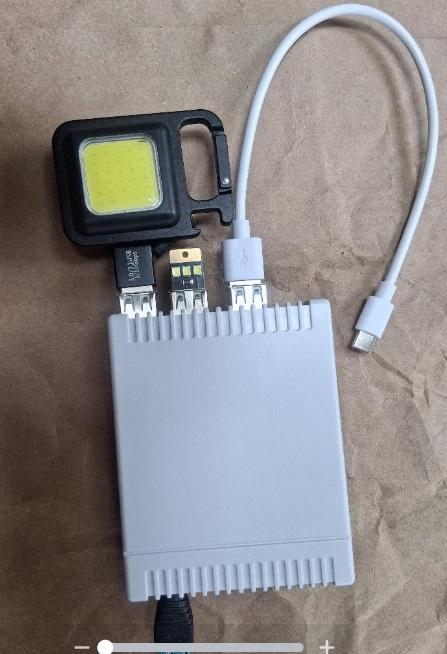 |
||||||
I can't honestly remember. I think the big case half was 3-4hrs and the little prints (one half + one panel each) were about 1.5hrs each. I wasn't really checking. The big one has a few errors. lol That little AE case looks good. :) I'm currently playing with a case design for a bench PSU using a 12V 5A module and a SK120X buck boost controller with IR control. It's looking promising. I already have a SK120X and, with the remote, it's quite nice to use. |
||||||
looks good ! Hoping to get 100 mm pcb case  There are "heated brass thread inserts" which are said to insert into plastic cases and have a strong thread (a soldering iron heats the the insert and it bonds in place), don't know if they are ok. |
||||||
I'll let you know eventually - I have some on order. :) I don't think I can get the inserts to work on a case that will take a 100mm wide board and will fit onto the bed of my printer. The problem isn't just the box width, it's the width of the "raft" that supports the workpiece. The printing surface is textured and might not work for direct to bed printing. I'd really need something other than that to leave the raft off, I think. It needs experimentation. |
||||||
I think I've managed to get a printable box that takes a 100x100 board and uses screws to hold the top and bottom together. :) It's a bit of a tight fit, even with 3mm screws. |
||||||
I've used the heated brass inserts, they work well, but their are a couple of things I've learned. 1. Use a tip for your soldering iron that you don't mind ruining (I had one that was way too large for soldering electronics - so I use that for my thread insert procedure). Somewhere along the line it will get melted plastic on it. 2. Model the hole in your 3D model to be a tiny bit smaller than the insert (<0.5mm). If there is too much plastic to push through (i.e. the hole is significantly smaller than the insert) and you have to push it hard into the plastic, then it can easily go in slightly skew, and even the tiniest bit off means it won't match up with whatever you are screwing it onto. 3. If you have a variable soldering iron, keep the temperature very low. I think I set mine to about 250C for PETG. Otherwise, if it's too hot, it will go in too easy and go all skew again. 4. Wait for the soldering iron to cool down before attempting to put your designated 3D insert tip on it. Okay, that last one might just be for me. Sometimes, I'm not too bright. |
||||||
I found a nice chart giving sizes and hole sizes fo various inserts. I'll try that as a starting point and see how it goes. A kit of bits for my T12 iron was pretty cheap so I grabbed one of those. I've seen reports that they are under-sized, but I reckon I could rotary file them all down in the drill to get a better fit - I doubt if I'll ever want M6. I saw a youtube video that had a couple of nice ideas. When putting the insert in leave it very slightly proud, turn the work over and push it the rest of the way on the bench top. The other was to file the head of a hex head bolt (larger than the insert) smooth and use that for the final push. Should be interesting trying them. |
||||||
I adapted a design from Thingiverse to the PICO 3 board using Tinkercad Case Edited 2026-09-30 01:47 by Martin H. |
||||||
I saw that but I didn't have the printer then. :) |
||||||
Hi Mick, Martin, I admit I see your 3D designs with envy. Then decided to buy a 5 euro RM2015S box. I am hopeless !! Taking the easy route, in stead of challenging myself to print my own casing. Regards from a total loser... Volhout |
||||||
Volhout That's the most pragmatic solution. It's more about making than having. But you can still use Mick's modified connector panels so they'll fit on the Picocomputer. I had been working on a solution similar to Mick's but, since I'm not as skilled at designing as Mick, I used the finished model for the Pico Computer 2. Adapting the connectors turned out to be the easiest way. cheers Martin |
||||||
Today I've been sorting out a box for the Elemento. It looks rather nice :) 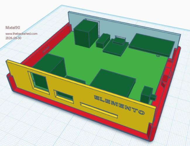 I'll do one for the PC3x next. It should be easy enough to modify the panels for the PC3 though, it's the same box. The bed size is still the ruling factor on any box wider than 110mm if I print using a "raft". The big box half in the picture is 120mm wide and the poor printer was hammering the end stops of the x-axis to print a "raft" 127mm wide (the physical size of the bed). I was quite surprised that it managed it. :) When the inserts turn up I'll do a test print to see how well they work. I'll also try direct to bed printing at the same time as it doesn't matter if a test print gets mangled. If anyone wants STL files for these just shout and I'll sort them out. |
||||||
But isn't the beauty of this hobby? We are not bound to do any one thing a specific way. It's absolutely fair game to make your own case, but it's also absolutely fair game to go buy a case as well. Nobody is judging, we're just having fun.  My first CMM2 case was a cardboard box. In fairness, it was a good cardboard box, you know one of those really sturdy ones that you get, and think "Wow, this is too good to throw out - but if I start hoarding the really good cardboard boxes for no reason my wife will kill me.". One of those.  Edited 2026-10-01 01:49 by PeteCotton |
||||||
Hi Mick, Is it okay with you if I post my own case model in your thread? Regards Michael |
||||||
I really like the RM2015 cases - they are my case of choice and far nicer than I can print. The main problem with them is finding the S size, I can find the M and L sizes easily enough. One of the reasons I wanted this little printer is so that I can print panels for the RM2015S (providing I rotate them 45 degrees on the bed) instead of having to order 10 PCBs larger than 100x100 from JLCPCB and either store 8 of them or throw them away. I tend to only build single projects. Can't see why not, Michael (good name, that :) ). |
||||||
@Mick, thanks! This is my attempt to design an enclosure (in Fusion 360) featuring a screwless lid and interchangeable panels - and not just for PicoMites. However, the lid isn't very secure! PicoCase MB04.zip 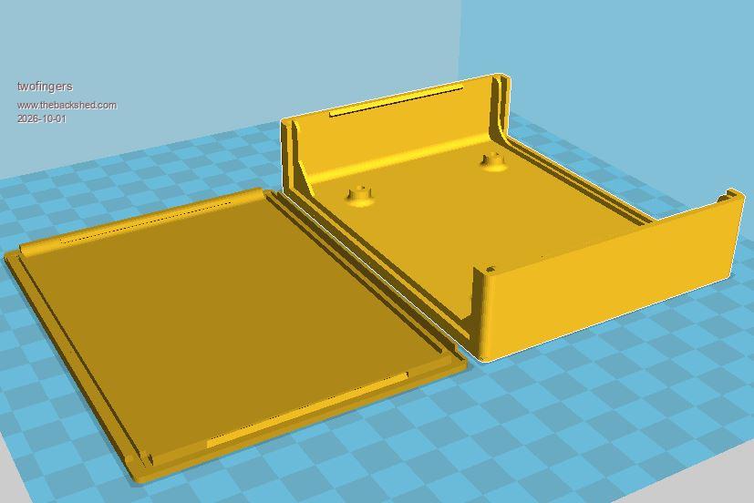 It is designed for use with heat-set inserts. Regards Michael |
||||||
It may be possible to avoid the need for inserts by using splined pillars. The gaps provide somewhere for the displaced plastic to expand into. My brother ran a plastic product and die design company for many decades and this worked well. The screw can cut a thread without splitting the pillar if:- a) the outer diameter of the spline is about 50% of the thread depth greater than the outer diameter of the screw b) the spline inner diameter is 30% of the thread depth greater than the thread inner diameter.  Scale this to make your pillar images a suitable size. > cls : circle 100,100,80,30 > for n=0 to 300 step 60 : arc 100,100,35,51,n,n+30 : next > save image "Splined_Screw_pillar.bmp", 0,0,200,200 > xmodem s "Splined_Screw_pillar.bmp" Tall pillars can have buttresses added to improve strength and rigidity. Edited 2026-10-01 10:57 by phil99 |
||||||
The problem there might be with the achievable tolerance that you can get with a 0.4mm nozzle. A much posher printer might manage it, but I'm not sure that a bottom end 10-yr old one may not. :) If the print is in ABS or PETG or, maybe, PLA+ then you can probably use ordinary coarse thread self tappers into ordinary blind holes for one-time or light use installation. PLA may be a bit fragile but I haven't tried it yet. It certainly works with moulded ABS (like most commercial boxes) but that's a bit too finicky for me to print. That's another thing. Adhesion between layers on the Z-axis. You don't want something that might tend to pull them apart. Inserts completely solve that problem. |
||||||
| Page 1 of 2 |
||||||
 |
The Back Shed's forum code is written, and hosted, in Australia. |


