| Menu | JAQForum Ver 19.10.27 |
| Menu | JAQForum Ver 19.10.27 |
Forum Index : Electronics : Another Inverter Build
Thanks for the input, plenty of options, I probably should have a tiny fan in there so any temperature rise can be taken up buy the main big heat sink, I will consider the 5v reg for the LCD.  I like the idea of the switch for the LCD back light, I haven't thought of that and it may well be better for night time use so not attracting bugs.  I still have to figure how I'm getting a little more temp than expected 65c, will keep you posted. |
||||||
The 5V voltage regulator that was getting a bit hot, after much checking, everything else was working as it should be, just that the LCD was using a little too much from the 5V regulator (in a box with no airflow) so a little mod was suggested by Wiseguy, "we can cut the track on the bottom side of the LCD +5V pin heading towards pin14 of U6 (HC86). If we feed a seperate 5V supply to the +5V LCD pin (and the 2 x LED buffer chips still connected to the LCD +5 pin) it will solve the problem." I also had to fit a 5V rail monitor to the LCD PCB, or it will corrupt the nano first time power is turned off.....I had to find out.  Testing has gone well, and it uses a little less power than before just running from a lab power supply, likely because its not wasted in heat. I ended up changing the Nano I had and put in an older Nano I had, seems to work better with the computer and has the bigger USB socked than the other one, will use it for running an LCD easy job for it. Now I did some of the Calibrations this morning using PUTTY on the Ubuntu PC (the Windows one still not happy) it works a bit like Tera Term, but haven't figured it out completely yet, when selecting menu items it will scroll down the list to where it should, but I couldn't enter the battery calibrations, typing in the new value, it had a flashing courser but no numbers appeared when typed, will probably sort that out later, but no problem I used the increment and decrement a few times and it worked a treat......All Good. 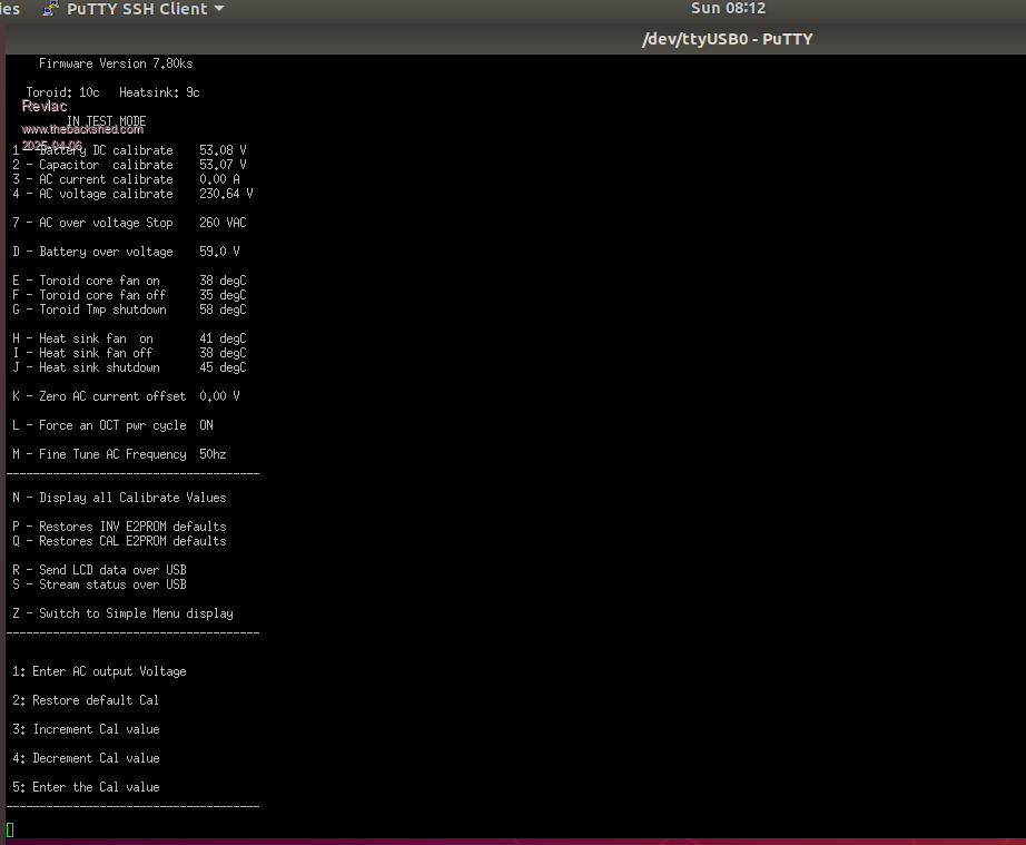 Voltage is good. 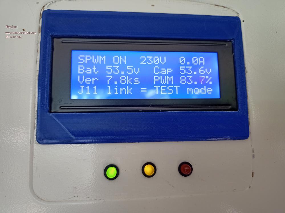 Still more work to be done, I should do the mod and remove the diode etc under the Nano controller, The Contactor jumping off and back on again, quite a surprise when not expecting it. |
||||||
Hi Aaron, great to see it running, I do have a few questions but no time as I'm heading out. The DEC/INC option is nice, can really fine tune it. There was some strange LCD corruption right from the start back when, and I assume you mean the Nano on the LCD board got corrupted. This is caused by keeping the Nano Reset pin connected to the USB Chip on the LCD Nano board, depending on the Nano board, the USB chip can really screw the Nano as power falls feeding garbage to the Nano serial port and corrupting Code via the Boot loader if that is still programmed in, mine are not and the Reset line is disconnected on both Nano boards in the inverter. It has Never glitched. Anyway, however you get that resolved is fine. Catch up latter . Edited 2025-04-07 16:59 by KeepIS |
||||||
Yes the nano on the LCD got corrupted, rapid flashing/Flickering of the LCD when powered down, how bad or fast depended on the regulator type, I put the 5v rail monitor (found the MC34164P-5G seems to work) on the reset pin 5v and GND on the PCB and the LCD still flickers but the nano is no longer affected. This nano is programmed with the LCD Hex code. I have another question for later, few things to check first. |
||||||
Make sure "Local echo" is selected in the Terminal Setup application, you want the Terminal Program to show the keystrokes that you type. BTW The latest version of the CODE is Version 8, the Latest changes.txt has the changes. Mainly LCD display corrections under certian fault conditions and a lot more info and index links added to the "Nano Hex and Menu.pdf" Version 8.0 Modify LCD Restart Inverter message Version 7.9 Auto Menu redraw correctly updates the Terminal display of the Menu on the USB Terminal application after any Setup calibration change. EDIT: The LCD screens will always flicker as the 5v rail slowly fades down, that is just the LCD backlight circuitry. That flicker has no effect on the Nano, however with a slow voltage decay and some noise added, it can cause the USB micro controller on the Nano board to reset the Nano Micro over and over while feeding crap to the Nano Micro serial pins, randomly leaving the Nano Micro unable to protect itself from Code corruption. . Edited 2025-04-08 11:15 by KeepIS Footnote added 2025-04-08 18:09 by KeepIS Obviously the supervisory IC will pull the Nano +5 volt down sharply and avoid the problem of corruption mentioned above, so does removing the Diode and Reset Capacitor on the Nano, on both the Controller Nano and the LCD Nano. I have four low cost Nano boards already modded and programmed to swap at any time, I'm still using the code development Nano in the Inverter, God only knows how many times that has been programmed and experimented on - it's still perfect.  |
||||||
Ok PuTTy Local echo and Local line ending was on auto, Changed Both to Forced ON, looks like that will do the job, works on the other computer will try it later, still have to calibrate the Amperage as I hadn't done it yet, I run the Hot water system for a few hours today and could see it was out a bit. I might as well mod and program couple of Nano's as well while I'm at it, put the later code on one of them. My other question, I made up another LCD PCB Carrier same as the WG44Rev2 board but on a prototype PCB, The wiring was done the same and the intention was to use it on the Poida MPPT charge controller with the serial code (nano_serial_to_parallel_LCD_2), Thought it should work straight up but it didn't, so the next idea to see If I had something wrong, I used the Inverter LCD Hex and it worked perfectly, I'm fairly sure its just a slight difference in the addressing or something?So the Charge controller is working but starts with the Inverter LCD message then the MPPT display kicks on, not a problem just be a bit funny if someone saw it start up and asked whats that Forgot to mention, I got the 5v rail monitors from RMS Components, they are local and flat rate shipping is a little better than others. |
||||||
Sounds like it's coming along nicely. FYI the LCD file "Nano Inv LCD.hex" is mainly coded to work with my Inverter code. It can auto detect the Baud rate change that happens when the Inverter is switched between 50Hz and 60Hz. After changing Mains frequency in Inverter Setup, it will not switch frequency until a full Inverter power down and Restart, at which time the LCD code detects the frequency change and displays correctly. The "LCD module" data lines are reconfigured for the Inverter LCD display board used by Wiseguy so it won't work with the (nano_serial_to_parallel_LCD_2) you mentioned. I don't use the rail monitors as the Nano boards are modded, so USB +5v and reset line are disconnected from the Nano micro. If you leave USB reset connected to the Nano micro, be very careful if plugging anything into the USB port on a Running Inverter - you will instantly reset the inverter. FYI I found the most accurate way to calibrate Inverter Current is with the Inverter running with 1.5 kW or more of load. EDIT: I can code and post a link to an LCD file that removes the Inverter heading if you like Edited 2025-04-09 09:51 by KeepIS |
||||||
Yeah definitely going to do the mod on the inverter Nano, all the capacitor boards are no on and I would like to avoid a reset under load at this stage, it survived so far, I have a pretty good 1.5Kw load and the power meter I have connected is good enough to get a reasonable measurement. If you want to code it that would be fine, my thinking is the little LCD board would be compatible and usable for the MPPT and any other builds that can use the serial nano LCD, I got an idea it could be used for future builds as well, If Wiseguy and Poida approve. I will post a follow up on the MPPT charge controller build later. |
||||||
|
||||||
Got it, Thanks Mike. |
||||||
I have modified a couple of Nano's following the instructions (nicely done easy to follow) KeepIS has posted, and the Nano running the inverter works as it should, no interruptions when using the USB port, what I did find, I have at least 3 different Nano's. The first Nano I had running the inverter, had some trouble with the usb driver on windows (posted earlier) it was the last batch of nano's bought it appears that they were the same as the last one in the Nano round up (Nano Board Info) and cannot be modified, so I had already decided to use them for the LCD duties before finding out about this, all is good. The other Nano's some are CH340P and others CH340PB as identified by AVRDUDESS, working no problems at all. Inverter is still running the test transformer and I know the turns ratio is a bit out so will have to make changes as expected, so taking a few measurements, at inverter idle the battery voltage 54v inverter primary voltage 31VAC the output voltage is set to 230VAC and the PWM 83% Now when running a load of about 1.6Kw the inverter primary is 32.8VAC and the PWM 91%, there is some heat from the toroid after an hour or so I was expecting some losses anyway, I have made these notes to see how the how it will improve when correcting the turns ratio and soon adding the other toroid etc. Its been cooking our dinner the last couple of nights and other things running during the day so its going well as it is. |
||||||
Thanks for posting your results, it's nice to know the Info was easy to follow and even better, the USB port can no longer upset a "running" Nano Inverter in ANY way. A good test would be to try one extra turn of heavy input cable to see how it effects the Duty cycle. Great to see its been running for a few days now. |
||||||
I will try something soon, I still have to remove the potted center from this toroid. |
||||||
I may have to put this some wear else but will start it off anyway. FOR those who want to use Linux Mint and AVRDUDESS to program the Nano. I think mab1 might be interested? I did get some info from here https://github.com/ZakKemble/AVRDUDESS Tried a few things but didn't quite get it working yet. The package that KeepIS posted earlier had a portable version. Not sure how I got it working or it was working before and I only just noticed. Screenshot, looks like it will work. 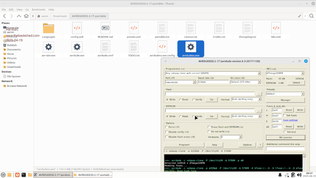 Also the version of Mint I used did not have the CH340 driver package installed, talk about that solution later if needed. |
||||||
Thanks revlac, I tried keepis's zip version on the imac and got: "Microsoft windows applications are not supported on os x"  I also found my way to the github page you referenced and downloaded averdudess 2.18 portable.zip ("portable for any OS") onto the imac - unpacked and got exactly the same error message  . Just wondering if I'm doing something stupid . Just wondering if I'm doing something stupid  I have also tried keepis's zip version on win xp and it runs , but then I saw the red error message in the box :">>> Averdude.exe ERROR: unable to start process. The specified executable is not a valid Win32 application" So I'm not sure what to try next  Edit: following your linky takes me to a different Github page - will try and pursue the imac route... Edited 2025-04-20 06:02 by mab1 |
||||||
With this 2Kw Toroid for the purpose of testing, measuring power in and power out, ordinary run of the mill meters nothing special. With HWS and fan running, inverter input 2080w Meter on inverter output 1877w I make that 90.2% So yes I'm making a fair bit of heat (after some time) at the Toroid |
||||||
House loads and Shed computers running plus HWS, efficiency is 98% PF is 0.988. Fired up some workshop machinery, all induction motors, NO HWS, and running at a similar power level to above, just over 3kW, 98% and PF 0.994. Running half an hour, each Toriods at 33°c. That is a totally unfair comparison as each toroid is only handling 1.6kW, and with very slow speed, silent assisted convection air flow, obviously the Fans won't switch to cooling at these levels. . Edited 2025-04-28 13:12 by KeepIS |
||||||
Well it was interesting this morning, Inverter output stopped somewhere between 1:00AM and 8:00AM, absolutely nothing running at all, used some power last night but battery capacity would have been over 90%. 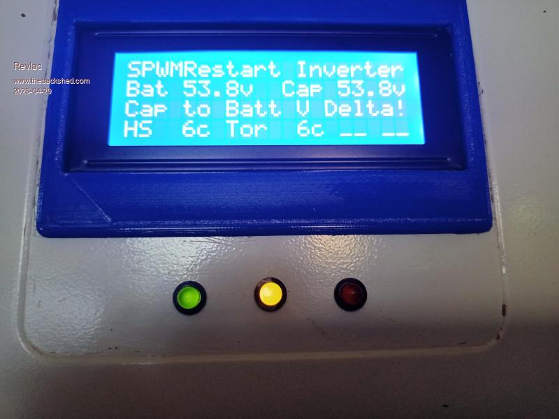 So I restarted the Inverter and it fired up until about the time the output relay turned on (give or take a few seconds) and noticed the LCD go blank, cant tell exactly when it went blank before taking a photo, the rest of the Inverter was running ok and output voltage was all good. 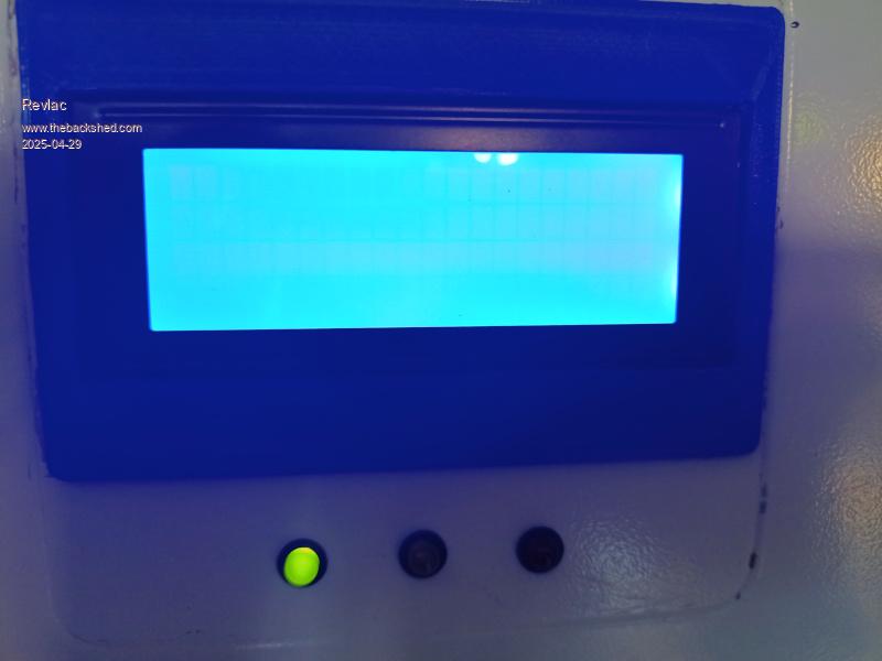 Restarted again thinking I will get a short video of it, but no its working perfectly now. I still haven't upgraded the main Nano from 7.8Ks to the latest HEX code yet, I have one done and put it somewhere. |
||||||
Are you running the latest version ? I had that situation out of the blue a few days ago, that's the reason for VER 8.1. I make sure it's a Delta error before stopping SPWM and requesting a restart. EDIT: Does the LCD have a boot loader? does it have the USB Reset Cap removed? BTW Mine also happened in the middle of the night with virtually no load, after 8 months of almost 24-7 run time. I know how it could happen on that one trip point, the fact that it happened once after all this time is a testament to the great stability of the ADC inputs and the little Nano in general, along with the quality of the controller PCB design . Edited 2025-04-29 11:17 by KeepIS |
||||||
Now running VER 8.1, on a different Nano, seems to make a slightly different transformer hum starting up, will run tomorrow as I had to put up with some noisy machinery today. The battery and capacitor values have been within .1volt all the time and remain strong under load. The LCD Nano has no bootloader, but the USB Reset cap might still be in place, don't know which cap it is on this nano.......(see photo) 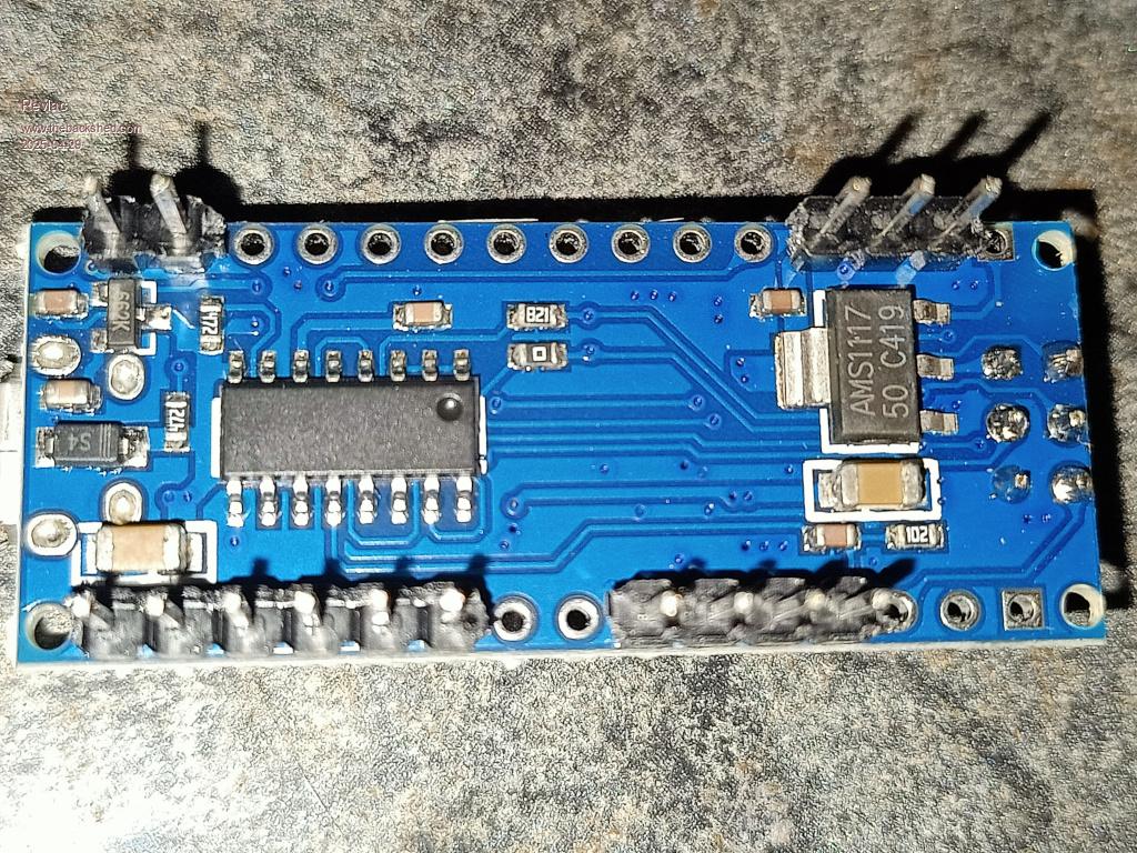 I'm sure we will learn more as more Inverters are built and running in the field, different builds and running different appliances.....makes it interesting. Its been running good all day and only just completed the calibration (VER 8.1 on the new Nano) tonight, using Linux Mint and PuTTY SSH Client Terminal. |
||||||
| The Back Shed's forum code is written, and hosted, in Australia. |

