| Menu | JAQForum Ver 19.10.27 |
| Menu | JAQForum Ver 19.10.27 |
Forum Index : Electronics : 150V 45A MPPT - roll your own
Hi, Didn't have much time last weekend, my wife is teacher and having a hard time preparing all digital lessons + keeping me and our baby alive, now she's got additional work, because a few classes are given on the school itself... So now she's doing both, so extra work for me in the household and around the house. About the power pcb V1.1, I noticed the current sensors are drawn on the bottom plane. But I soldered them on the top side. The wire routing is correct when they are soldered on the top side. Also uni-directional sensors could be used the way it is now, Pin 4 (+) is on the input, Pin 5 (-) is on the load side. I'm going to change the footprint to the topside. The footprints of the screw connectors are also put on the topside now, as they were drawn on the bottom side. I've changed hole sizes to 8mm instead 6mm to allow the use of those 4mm Allen Screws. I've changed component values to the ones I've used. What would happen when I use 1000uF caps? Don't worry you don't need to adapt the code for me, I'm happy @ this moment to regulate my input voltage with a fixed setting, it's very simple but with high overall efficiency. Edited 2020-05-11 18:59 by nickskethisniks |
||||||
I started to try to sketch the pcb and modifications....sheesh, and I see Nicks has been working on the original too, was trying to save the effort. Here is the schematic and sketch if Nicks or anyone wants the database files to suck into easy eda just ask. Schem.pdf Sketches.pdf I wanted 3 Fets for a job - you dont have to load the 3d one, the finished board size is 190mm x 140mm. I also only used 4 caps for the output - I reckon that is plenty. Just noticed 2 little glitches where tracks join to ground plane, now fixed. Input from solar on the left output to Bat on right, havent run the rule checker yet - still a bit left to do. Edited 2020-05-11 19:22 by wiseguy If at first you dont succeed, I suggest you avoid sky diving.... Cheers Mike |
||||||
I think we've got ourselves a V1.3 or whatever you want to call it. Something else I'm wondering about but forgot to do research on. As I mentioned before I have wired my solar array 2S10P, is it wise to put diodes on the end of each series string before connecting the strings in parallel? Before I wanted to make a pwm controller and later mppt controller I wanted to do a simple regulation. By simply connecting more or less solar panels to my battery. I even made some simple pcb's that have a mosfet and diode on them to do a crude connect or disconnect of each string. Let me see if I can dig them up. |
||||||
It looks a bit sexier in colour, here are 2 screenshots. I included the separate 12V connector Az asked for. The noisy and quiet grounds are tied together in the upper RHS where a 0.1" and 0.2" spaced pads are allowed for a ferrite bead if needed. This was definitely more fun than sorting out my workshop....... 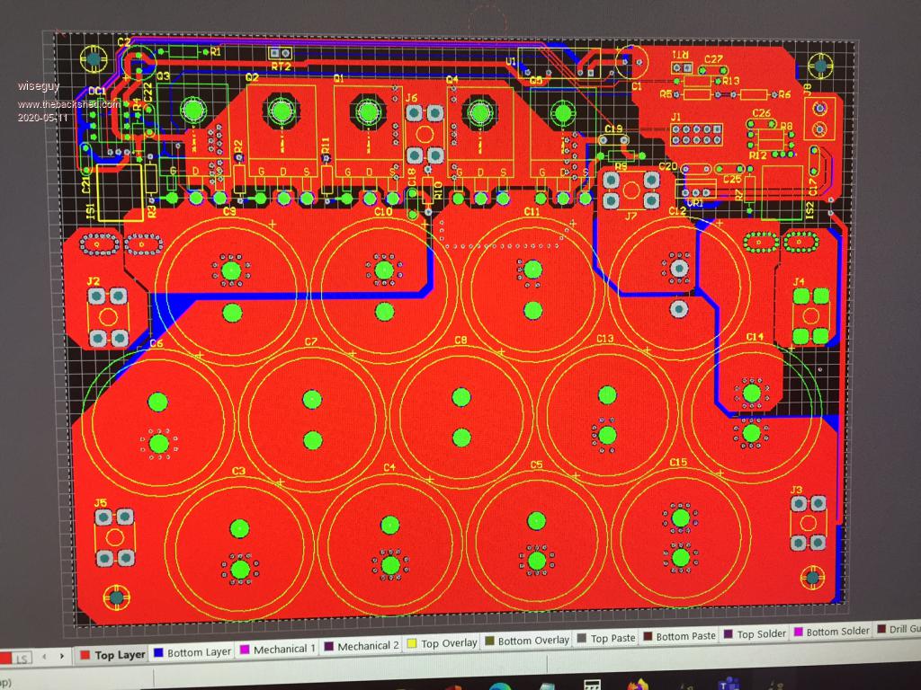 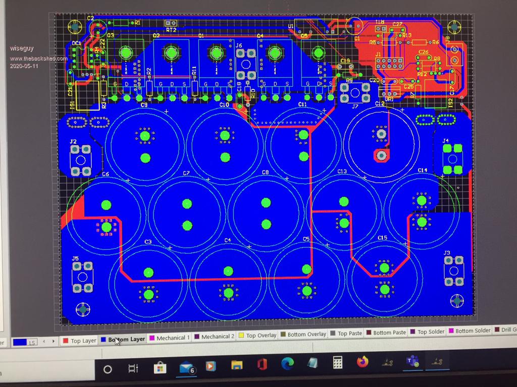 Edited 2020-05-11 19:48 by wiseguy If at first you dont succeed, I suggest you avoid sky diving.... Cheers Mike |
||||||
Nicks/Poida Will this have a equalizing charge option? |
||||||
Mason, the firmware is likely to have very simple functionality. I want a simple charge controller. My battery is sealed lead acid so equalise is not needed so much, if at all. And if needed, only a small increase above absorb voltage. How often would think you would equalise your battery? Once a month? Could I have a bit of info of the requirement so I can see if it fits with the limitations of the project. |
||||||
Poida, yes would only equalise once a month if I remember to do it lol, I don't want to complicate your build. I'm sure it was not easy up till now. Thanks |
||||||
I think most flooded batteries would be similar, but mine requires 64v for 2 hours. Perhaps a different nano could be used just for EQ days? Normal operation would be with the std nano, when an EQ was wanted the spare nano could be plugged in, does it's EQ charge and then goes to float. Std operation is get to 57.6v bulk charge Stay at 57.6v for 2 hours absorb charge Then go to 54v float. So if you went down the separate nano route you would have the same process with different voltages. EQ get to 64v bulk EQ stay at 64v absorb for 2 hours then go to 54v float. Would that be feasible? |
||||||
I would have one firmware, which is to be configured by the end user to suit their needs. There will be some defaults, maybe no EQ unless configured to run for x hours at y voltage every z days. How measure time with a Nano? We will need an RTC and that will need to be configured correctly too. |
||||||
All you really need is to push a "cell equalization" button, and start up some subroutine that runs once only. |
||||||
That is a much better solution. The routine will have EQ voltage, time to hold it at EQ both defined via the menu and stored in EEPROM. It will attempt to complete the EQ period and record how much time was spent at EQ, reporting the result on the LCD/serial console and storing that data in EEPROM. I see a few situations. 1 user presses EQ and it starts. Then we run out of sun. So the code will store how long was spent at EQ which can be read back via serial console. This permits user to verify time spent at EQ. 2 user presses EQ and it starts and completes. Again how long it was at EQ is recorded in EEPROM which can be read via console. 3 user presses EQ again, while EQ is running. Nothing happens. Not even extending EQ duration. |
||||||
Or you could just have a run time counter that stops when the battery voltage falls below the equalization voltage threshold, and starts up again when the sun comes back. When total equalization time is reached it reverts to normal operation. It need not be over complicated, its not a vital function. |
||||||
No worries, Warp. here is the first hack at the brainboard PCB. 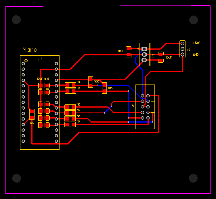 I like the very short tracks from the low pass filter to the ADC pins. All I want, really. The rest just needs to work well enough. |
||||||
I will repost this when it is fixed. Edited 2020-05-12 16:11 by wiseguy |
||||||
here is a better attempt. The board is only 75mm x 50mm $5 for 10, I think I will order them. There is a connector for 2 user switches. Maybe only need one for EQ. Just give it 12V referenced to battery ground and go. 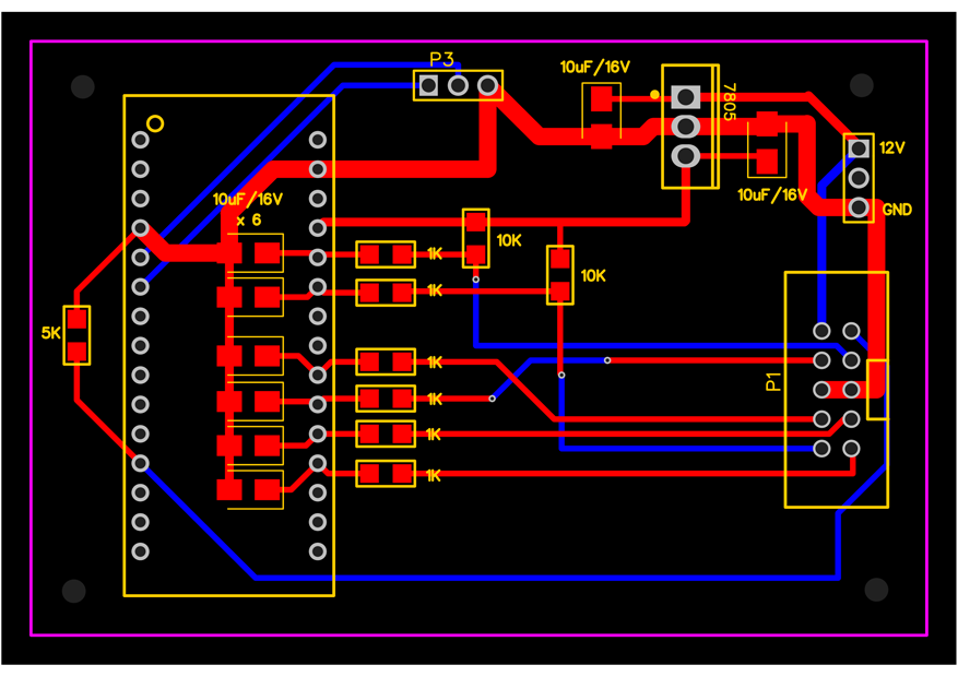 Edited 2020-05-12 16:26 by poida |
||||||
OK Take 2 the first scheme had a fet/diode issue so I added a relay instead. Good effort Peter - layout scheme is electrically good. I have been thinking about a scheme to stop backfeed discharge Here it is Backfeed stop B.pdf It works as follows. Its night time nano is off backfeed stop fet is off. Its daytime dcdc nudges nano with 12V and says wake up. Nano says cripes turn on backfeed relay and start charging the battery Its dusk nano says hmmm no charge happening for a while lets turn off backfeed fet/relay. Oops this kills the nano stone dead, as it had now been running on backfeed through the MPPT DC/DC (which was also backfeeding the panel) it also obviously stops the backfeed. Its daytime dcdc starts nano again etc It looks like it should work and inspire some maybe better/simpler solutions ? |
||||||
Peter, before you order the PCBs - I will be sending you an email in a few minutes. There are a few points to discuss first (ie providing) pulldowns on your PCB for the thermistor inputs if they are fed from 5V on the MPPT board ? And a couple of other things. |
||||||
the tristar I have , you hold the button for 5 sec for eq mode and 1 sec for reset or cancel (1 sec cancels eq mode or over voltage) |
||||||
Hey wiseguy the opto driver being used in this circuit is perhaps a little old and under-rated for driving 2 fets, let alone 3; the manufactures spec is +- 1.5 amps, but recommended is only 0.5 amps. An uprated plugin compatible device would be FOD3182 with 3 amp drive and give better efficiency. Cheers Mike |
||||||
Mike thanks for your post - I dont have any of the TLP152 series Opto FETs in my go to bits personally. I only use the FOD3180 as a minimum driver - thats what I used in my inverter albeit with external current boosters. The FOD3182 is definitely what I would use for 3 FETs. I tried to just present the schematic as presented to me and as tested by Poida etc to date - I sometimes feel like the tail wagging the dog a bit so I try not to impose my thoughts and limit my unsolicited advice and just do what I feel is right for me in what I build. The PCB files posted here by me are a work in progress - it was not meant as a finished design, just to inform/show anyone interested in my proposed layout, still tweaking it but should be ready later today - there were a few bugs in the earlier posted artwork. |
||||||
| The Back Shed's forum code is written, and hosted, in Australia. |


