Posted: 01:16pm 21 Aug 2025 Copy link to clipboard
Volhout Guru
Hi Kevin,
Yes, I have seen it, I even commented in it. I don't think it is a product that will produce a good function generator, but I was curious to play with it. For the 5 dollar including shipping, it is a toy.
But when I get it, and I see same behaviour, and I find a solution (I will try to fix it, that is me, trying to fix things), then I will put that on the forum.
And _if_ I get it improved, I will add an output stage (+/-10V). Since 3.3V is not enough.
Volhout
Posted: 08:22pm 21 Aug 2025 Copy link to clipboard
Bleep Guru
Excellent :-) I'll be very interested if you can improve it. Regards Kevin.
Posted: 02:20am 22 Aug 2025 Copy link to clipboard
smoketronics Newbie
@ville56
Yes, at my age I can't afford to lose much more. There won't be anything left :)
Looking at it with my scope it appears that CS does go high a couple of clock cycles before data is sent. I am not sure if there is a problem with PicoMite or if it is with the AD9833 needing CS to go high sooner. But I did make a note in my printed manual. The good news is that I can finally play now. It works to put that dummy message in a sub and call it before sending data
VY 73, Steve - N7IO
Posted: 08:00am 22 Aug 2025 Copy link to clipboard
Mixtel90 Guru
Hehe.... too late to worry about that here. :)
Would a 10K pullup on CS help?
Posted: 11:00am 09 Sep 2025 Copy link to clipboard
Volhout Guru
Hi Kevin,
I received my 9833 board, and got it working (just Geoff's MM2 version). The square wave distortion is not from the 9833 chip, but from the potmeter/opamp circuit. I'll see what can be done about it. The potmeter (value 10k) does not help a lot to achieve fast transitions. Maybe I can find a pin compatible, software compatible potmeter that is 1k or so. First I need to do more analysis.
UPDATE: it is caused by the opamp. I'll order some OPA356's and we should be good.
Volhout
P.S. The 9833 is a nasty device, in that it uses a numerical fractional divider, and not a PLL. Especially visible when outputting higher frequencies. If you set the frequency to 1.02MHz, you get 1 cycle 1.00 MHz, then a cycle 1.04 MHz, then a cycle 1.00 MHz, alternating. Average it is 1.02 MHz, but looking at a spectrum analyzer you see 2 peaks at 1.00 and 1.04. sh*tty design. Anyway, we will see what we can do with it. It is a toy. Edited 2025-09-10 00:05 by Volhout
Posted: 03:09pm 09 Sep 2025 Copy link to clipboard
Volhout Guru
Kevin,
If you do not want to solder a new opamp....
The problem is that in square wave mode the input of the opamp is driven with 2.5V input signal (211/256*3.3V), and the opamp has a gain of 6x (the 9833 sine and triange wave signals are small signals, the square wave is huge (rail to rail).
So the opamp input is over saturated, causing this type of distortion. If you (software) limit the input signal to the opamp in square wave mode, the opamp amplifies linear. I have managed that by adding 1 line in the program to send a different setting to the attenuator, while keeping the display at 100%).
You will not see a perfect square wave, since the opamp operates in linear mode, and this opamp (AD8051) has a small signal bandwidth of 110/6=18MHz. Large signal bandwidth is typically less. To get a better square wave, we need a faster opamp. i.e. a OPA356. But this may be good enough for many.
Regards,
Volhout
Posted: 07:09pm 09 Sep 2025 Copy link to clipboard
Bleep Guru
Hi Harm, Ok thanks for the info. I'll have a play tomorrow :-) Regards, Kevin.
Posted: 08:16pm 10 Sep 2025 Copy link to clipboard
Bleep Guru
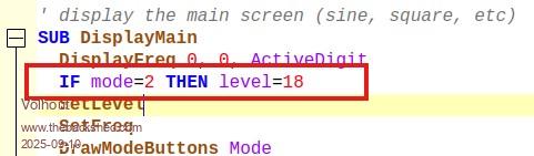
Hi Harm, I have modified as you suggested and it definately makes the Square wave better, presumably it was being over driven before. I changed my level to 18, because it gave me a 3V p/p square wave, which is the same as the Sine wave at 100%.
If Mode<>LMode Then LMode=Mode If Mode=2 Then LLevel=Level Level=18 Else Level=LLevel EndIf EndIf
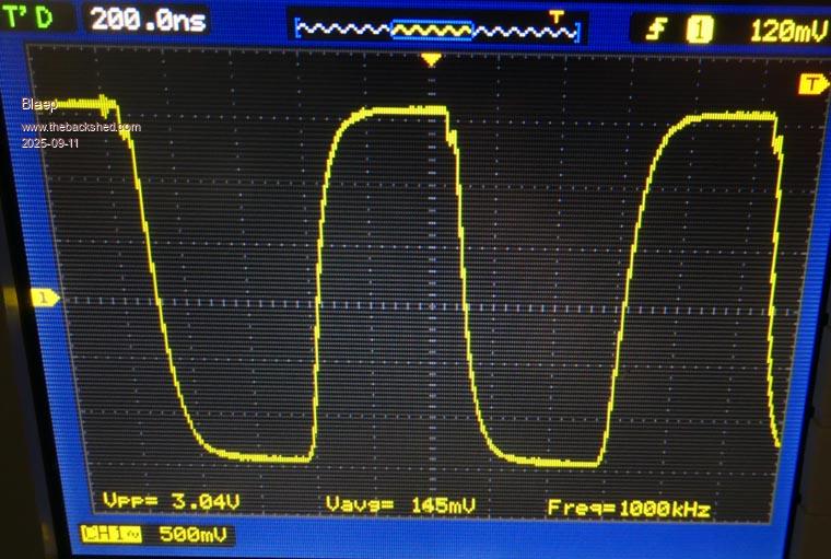
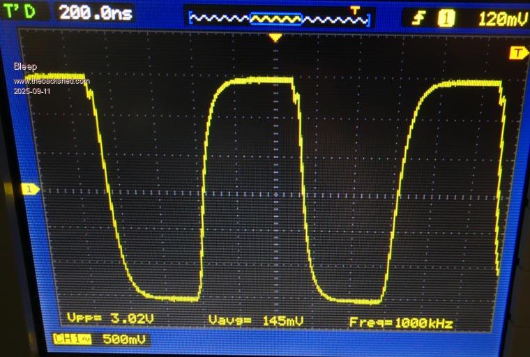
I do find there is a strange 'jitter' on the square wave, for want of a better word, I assume it is to do with the crystal divider, though I still get a very slow change, about every second even if I select 1MHz, which I would think should be a perfect devisor frequency. If you look at the following 2 images, taken about 1 second apart, you can see that the falling edge moves, the rising edge is steady.
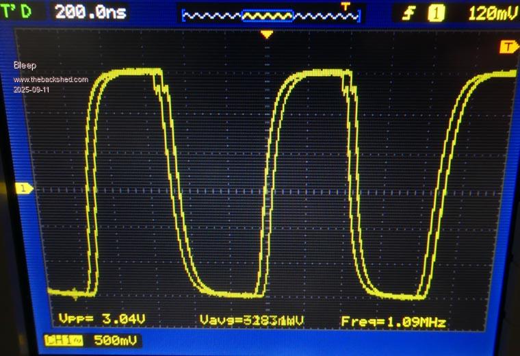
This image is when I select 1.1MHz, which would be a devisor problem.
Otherwise the Square is definately an improvement, Thanks. :-) Regards, Kevin.
Posted: 07:19am 11 Sep 2025 Copy link to clipboard
Volhout Guru
Hi Kevin,
The "jitter" is exactly what I saw (the numerical divider alternating between 24 and 25 (or 25 and 26). However, this seems absent in the sine and triangle (the DDS signals) waveform.
I copied your solution on the software. Maybe Geoff can apply that minor code change also to the code on his web page.