| Menu | JAQForum Ver 19.10.27 |
| Menu | JAQForum Ver 19.10.27 |
Forum Index : Microcontroller and PC projects : PicoMiteHDMIUSB motherboard reference design
Hi Plasma, can you also sigh me up for one. Pluto |
||||||
No kidding....I worry about being the annoying one because even though all the info is here on TBS, one needs to piece stuff together. Yeah, I think I still prefer the idea of VGA but I don't remember if I lose something. I only recently became aware of VGA-to-RJ45 (thanks Mixtel90) and this makes things much cleaner for my applications. Yeah dynamic is the word but I'm loving it  |
||||||
Same procedure as every ‚year‘  if you tell us how we can pay for your work then please add me to your list. |
||||||
I respect the pcb designers boards but they're ephemeral. try mode 3 on vga. not much mention but why bother with hdmi if vga can do same.. better? |
||||||
Mode 3 VGA can only display 16 fixed colours, map just selects amongst the 16 Mode 3 HDMI can display 16 out of 32768 colours, mode 4 32768 colours, mode 5 256 colours out of 32768 colours |
||||||
All Apologies, but please note the silkscreening for the edge connector I/O is incorrect on the top of the board (correct on the bottom). In each case the pins are swapped "GP28 GP27" should be "GP27 GP28" I'll reissue the gerbers once I decide how to replace the audio circuit inductors as JLC are currently showing these are out of stock even though LCSC have over 2000 in a different warehouse. |
||||||
star you are matherp. vga mode 3 is ideal hi res colour. and everyone got vga board so olimex bought for hdmi was a waste but gonna try it as vga cos it got audio and sd card reader. which uf2 vga usb 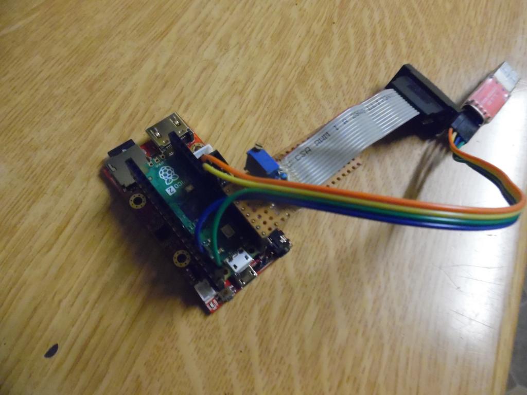 |
||||||
Two thoughts: 1. Place a link in the +5V feed to the edge connector. Novices and experienced people all make mistakes. Ability to minimize output pins being destroyed or worse the pico2. 2. Through-hole vias for the pico2 to allow for socket mounting. A pico2W on the way would be nice to swap in at some point in time. This admittedly makes the front panel 'program' micro-usb socket redundant and also assumes you will support the pico2W. I would be happy to "open the case" to re-program the pico. Makes no difference to those happy to solder the pico to the PCB. Best regards led |
||||||
Soldering the Pico down reduces the lengths of the traces to the HDMI socket, allowing more chance of widescreen working. At those frequencies you really need to get all the traces the same length and the Pico design doesn't lend itself to that. When the bare chips are available that problem will be much easier to solve but in the meantime getting the Pico as close to the board as possible is the best compromise. It's not just a case of keeping the cost down, although it also helps in that. My current designs use the same case but the Pico is socketed and you have to open the case to program it. However it isn't all SMD by JLCPCB and you are going to have to learn how to solder a HDMI socket. lol Delta (still in design and not yet announced) attempts to give better equalization to trace lengths for both HDMI and USB (although it's less critical with USB 1.1). |
||||||
This doesn't work. The USB hub circuit needs a connection to the USB connector on the Pico2. This is achieved by connecting to TP2 and TP3 on the bottom of the board. Without some unpleasant hack wiring there is no access to these pads if socket mounted. 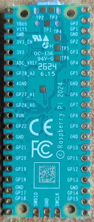 The 5V output is deliberately located next to the I2C connectors to provide power if required to an I2C module. Note that these pins are only powered if the board is turned on and in that case the Pico2 pins are 5V tolerant |
||||||
Attached V1.1 gerbers BOM_Board1_PCB1_2024-09-30.zip Gerber_PCB1_2024-09-30.zip Changes: Fixed top side silkscreening for I/O edge connector Changed Audio inductors for an in-stock part 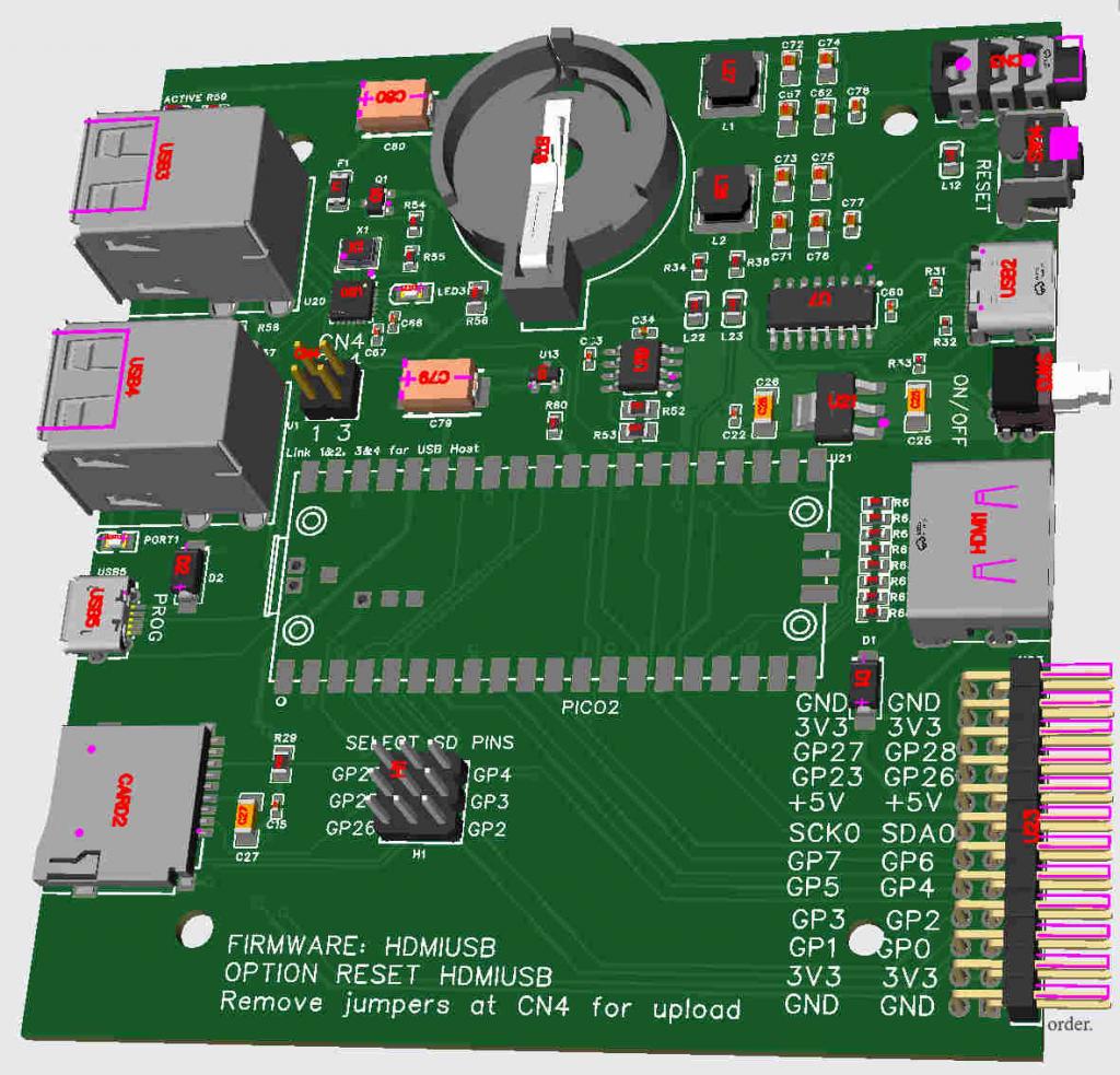 Edited 2024-09-30 19:14 by matherp |
||||||
Is there a reason why you did not simply design the 2350 chip etc into the board rather then using the PICO2 module? You did that with the 2040 VGA board I seem to remember... I'm probably missing something very obvious. |
||||||
Individual chips (RP2350A or B) cannot be purchased yet. Volhout |
||||||
AHHHH!!! Yeah, that would kinda explain it!!!  |
||||||
Hi Grogster, If I go back to similar changes made on the RP2040 platform (when going from a pico modules, to an onboard chip, I expect that Peter will also make use of the fact you get's access to the GP23/24/25/29, and will make both sets GP2/3/4 and GP26/27/28 available to the expansion connector. In this design either GP2/3/4 or GP26/27/28 are used for the SD card, and you put jumpers to select what pins are used. Regards, |
||||||
The TCM809TVNB713 supervisor chip (C626626) is currently out-of-stock. If ordering you can replace is with TCM809SVNB713 (C171841). Just edit the BOM. The footprint is identical. |
||||||
Plasma, Sign me up for one. Matthias |
||||||
My first question is, how do you solder these pads when the board is directly on the PCB? The holes for socket mounting are optional. Either the "hack" wiring or what about POGO-PINS in these locations? These are even available solderless ... https://www.mouser.de/ProductDetail/Pimoroni/PIM330?qs=qSfuJ%252Bfl%2Fd7kN0DmBsa0SQ%3D%3D&mgh=1&vip=1 Matthias |
||||||
First post in the thread |
||||||
You make sure there is plenty of liquid flux in the area over the pads (and, if possible, just a tiny bit of solder paste). Put the Pico on the PCB, line it up and solder a couple of opposite pads while holding it tight against the board. Then turn the pcb over, add more liquid flux over the pad holes and heat them up, adding a bit more solder. When it gets hot enough the solder will be drawn through the hole by capillary action and flow into the miniscule gap between the Pico and PCB pad. You really do need the flux for this. It makes a big difference. The solder paste seems to act as a "starter" to get the main solder to flow. The connection will usually work wine without it though. Once one of these things is soldered down it isn't coming off again in a working condition and with all the traces still on the pcb. Just warning you. :) TP5 is a nice pad to have too. |
||||||
| The Back Shed's forum code is written, and hosted, in Australia. |

