| Menu | JAQForum Ver 19.10.27 |
| Menu | JAQForum Ver 19.10.27 |
Forum Index : Microcontroller and PC projects : A selfmade breadboard friendly HDMI plu
The simple resistor-capacitor PWM filter is actually very poor. It will extract audio, it's true, but the frequency response is poor and at the top end there is virtually no reduction in the 44kHz carrier signal that the PWM uses. That means that it makes a mess if you feed it into a decent audio system - and it's quite possible that it could damage some tweeters. Volhout's filter cuts off sharply at the top end, removing almost all the carrier frequency. It's worth using even if it means buying a few cheap components off ebay or AE. You can get away with the simplest filter if you are sticking to little PC speakers or headphones. . Edited 2025-06-07 06:02 by Mixtel90 |
||||||
Thanks Mick for that info, I got the coils and capacitors to build Volhouts version. Next for me is to get the sdcard and system spi running, as well for i2c and the ds1307..I know poor chip :) |
||||||
@Stan I would see sdcard,rtc and audio as mandatory..it's so easy and cheap in any way(except my VS1053 :( ) |
||||||
I rather like the VS1053. It works well. Of course there are other choices too: The MCP DAC chips - your choice of 8-bit, 10-bit or 12-bit audio and takes up less space than Volhout's filter. It costs more though. Puts a bit of load on the processor but the 2350 probably doesn't notice. Tucks away nicely underneath the Pico. :) I2S audio too (PCM5102 for example). I have a couple of modules but haven't used them yet. Cheap and, reportedly, excellent audio quality. I'd avoid PWM audio now. It's not easy getting rid of CPU noise on the audio (careful routing of signals and grounds, using a linear regulator to get rid of the switcher). Digital audio (any version) makes it so much easier. |
||||||
nothing is mandatory but yeah you're supposed to have an sd card and audio and use usb hdmi and have a usb keyboard and mouse. do you? if I use a usb to ttl then that will power the pico, pin 40. yhat will drive the usb kb/mouse.. even a wireless usb dongle works for a kb/mouse screen. problems are sd card needs 3V so want it on one side of board ,not OPTION SDCARD GP22, GP6, GP7, GP4 there is a lot of difference from just hdmi and usb hdmi |
||||||
it was never a mp3 player or a retro game machine. it was supposed to be a boot to basic design. why? |
||||||
It still is. You just take it as far as you want to go. You can still use it as an embedded controller with no display or with some sort of minimal or touch screen display. It can still scan a numeric pad. It's just as valid to use VGA & a PS2 keyboard now as it ever was because it's still a "boot to basic" machine. It still has no OS. I's just that now you can do other things *if you want to*. It's all optional. Nothing has changed fundamentally. :) You don't need to use the Library. You still have flash slots and drive A: built in - which means that you don't need a SD card in some cases. That's the beauty of the PicoMite. It can be anything from rock bottom up to a pretty amazing sound and graphics machine. It's all your own choice. :) |
||||||
Hello :) This is my work of today. SDcard, i2c/RTC and audio working: 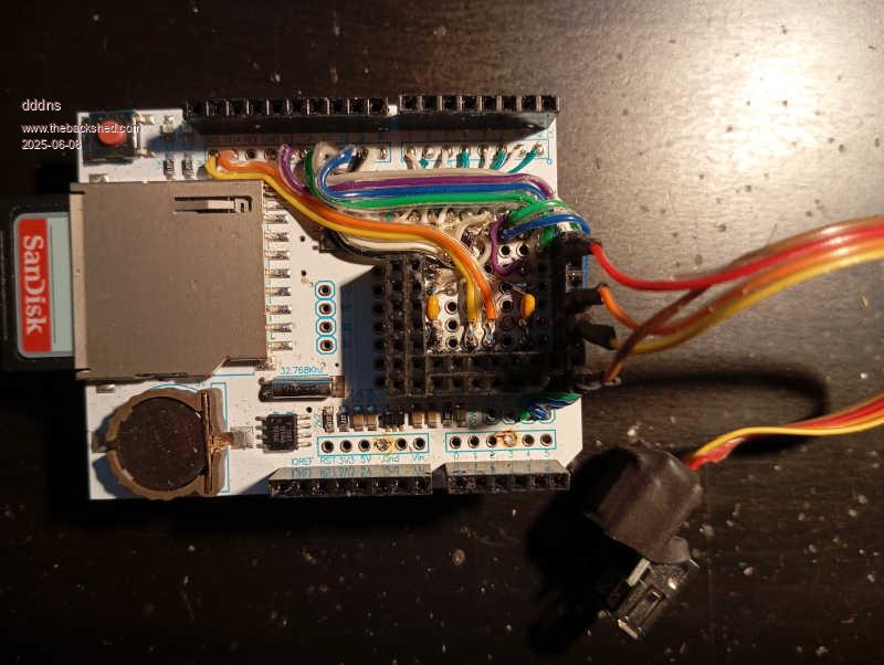 Up to now I didn't touch the logger shield, it runs with 5V and a level shifter.. 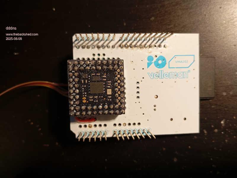 And I implemented @Volhout's audio filter: 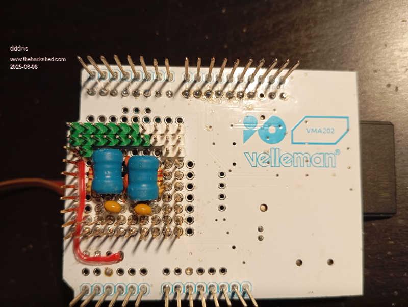 :)) |
||||||
Impressive and compact. There was just enough room to put the pga. But this is not doable for the average shedder. Volhout |
||||||
That little board that I posted a pic of above is about 52mm square, although it's using the Pico rather than the PGA2350 so there are less GPIO pins available. It should overclock ok though. :) The Arduino UNO is 53mm x 66mm usable area. Also, the blank PCBs are 5 for about £4 delivered. That Velleman board is £7.37 for one (plus postage) here. I know there's a lot of fun in squishing the components into an available space. I just prefer to do the squishing virtually rather than on the fly with the soldering iron. :) I used to do a lot of hardware squishing before I discovered SL6 and cheap PCBs. lol |
||||||
The logger shield I bought at a real Conrad store once they still existed 10 years ago. BTW, the batterie is still good :)) These are my very last parts to do something, and as the parts are only few I saw the puzzle pieces.. I have a mill but no more bits or raw material.. This is my very last tinkering I promise! I will quit this non-sense! |
||||||
Back to this Prototyping(@Volhout) and one more to the concept. Pins GP0 to GP19 are hard wired but still accessible from outside in these arduino pin rows. All complete free pins end up in the middle. GP8 and GP9 will be for serial and GP10 and GP11 are left. All pins from GP20 to GP46 are free in a row and I will create an adaptor for the 16-bit ssd1963: > list pins GP0 1 Boot Reserved : SPI SYSTEM MISO GP1 2 Boot Reserved : SD CS GP2 4 Boot Reserved : SPI SYSTEM CLK GP3 5 Boot Reserved : SPI SYSTEM MOSI GP4 6 Boot Reserved : SYSTEM I2C SDA GP5 7 Boot Reserved : SYSTEM I2C SCL GP6 9 Boot Reserved : AUDIO L GP7 10 Boot Reserved : AUDIO R GP8 11 OFF GP9 12 OFF GP10 14 OFF GP11 15 OFF GP12 16 Boot Reserved : HDMI GP13 17 Boot Reserved : HDMI GP14 19 Boot Reserved : HDMI GP15 20 Boot Reserved : HDMI GP16 21 Boot Reserved : HDMI GP17 22 Boot Reserved : HDMI GP18 24 Boot Reserved : HDMI GP19 25 Boot Reserved : HDMI GP20 26 OFF GP21 27 OFF GP22 29 OFF GP23 41 OFF GP24 42 OFF GP25 43 OFF GP26 31 OFF GP27 32 OFF GP28 34 OFF GP29 44 OFF GP30 45 OFF GP31 46 OFF GP32 47 OFF GP33 48 OFF GP34 49 OFF GP35 50 OFF GP36 51 OFF GP37 52 OFF GP38 53 OFF GP39 54 OFF GP40 55 OFF GP41 56 OFF GP42 57 OFF GP43 58 OFF GP44 59 OFF GP45 60 OFF GP46 61 OFF GP47 62 OFF > option list PicoMiteHDMI MMBasic RP2350B Edition V6.00.02RC25 OPTION SYSTEM I2C GP4,GP5, SLOW OPTION FLASH SIZE 16777216 OPTION COLOURCODE ON OPTION PICO OFF OPTION RESOLUTION 1280x720 @ 372000KHz OPTION DISPLAY 30, 80 OPTION SDCARD GP1, GP2, GP3, GP0 OPTION AUDIO GP6,GP7', ON PWM CHANNEL 3 OPTION RTC AUTO ENABLE OPTION DEFAULT FONT 3, 1 OPTION PSRAM PIN GP47 The device will be 25mm in height including housing. |
||||||
Hello :) The last components missing are USB/UART, USB for the Pico and an audio socket. Now I take it as challenge and will not modify the board and need something to mount the missing parts. I took Freecad and designed a housing: 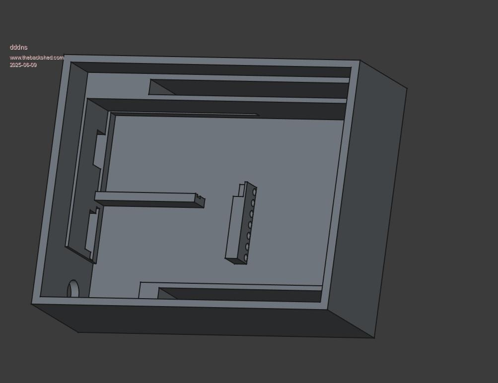 housing1.zip Last material I have is PLA.. very ugly in every way, what can I do.. 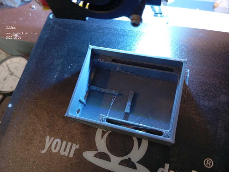 I can only estimate how much it also shrinks, a pain 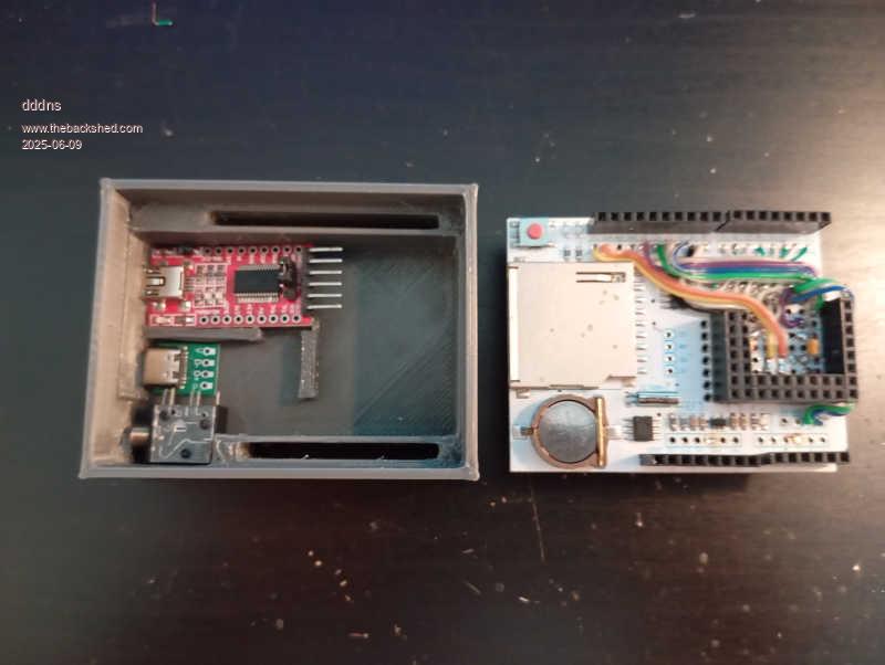 After some Kg printing I about know now..it fits well :) 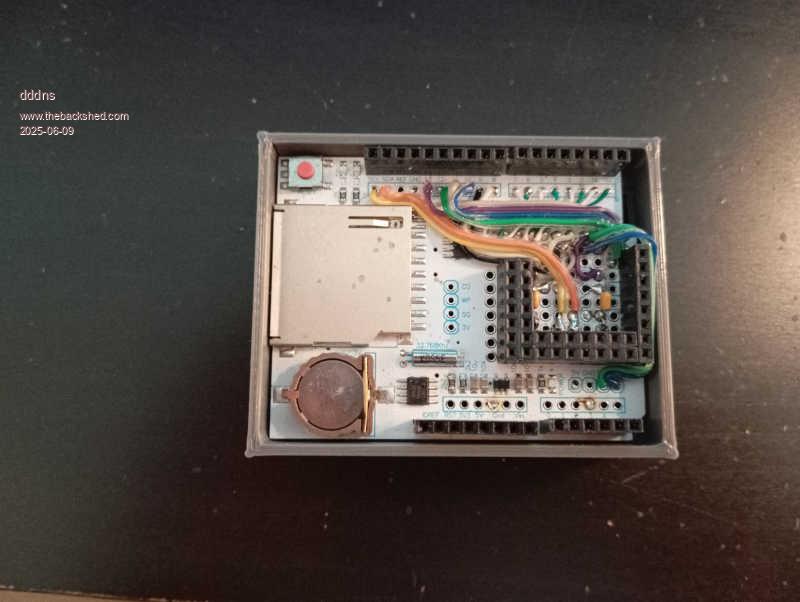 It can have a docking whatever :)) 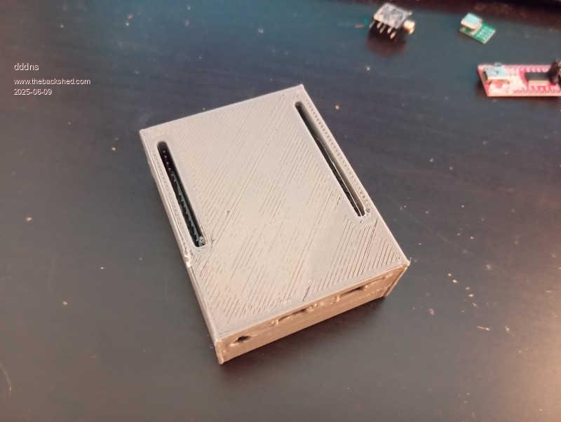 |
||||||
Well tinkered! :) |
||||||
Thanks Mick. Three things left to be done, to fit in the new parts and build the uplink to the board. Then the labeling with inkscape and acrylic covers. Let's see, at least three days of work, I hope by next weekend. |
||||||
Hello :) I have a little toy mill I use for (retro)fitting and this is the only tool I will use to finish it. Everything is handmade and just in time, this morning: 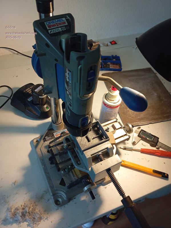 Cleaned the print and went over all planes which I want to have "precise": 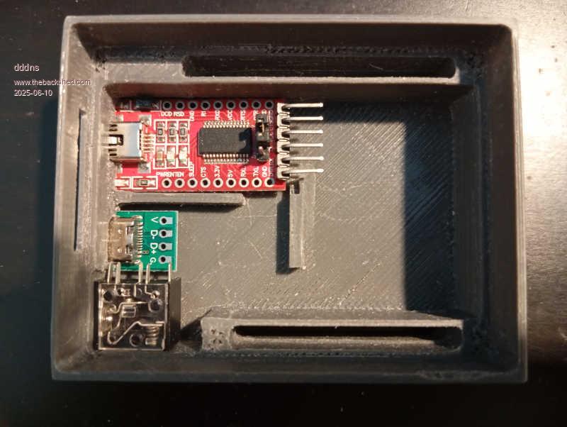 Leveled everything and milled a 0.8mm deep pocket: 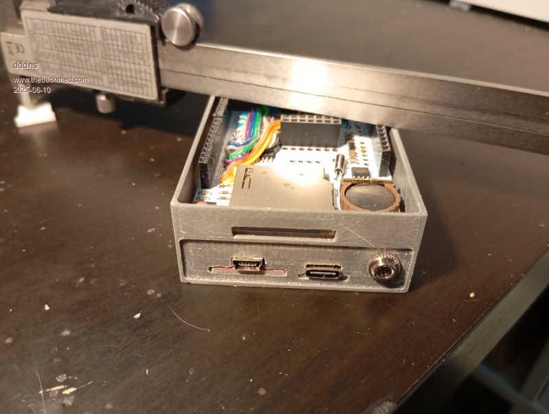 The "docking pins" are 1,5mm below: 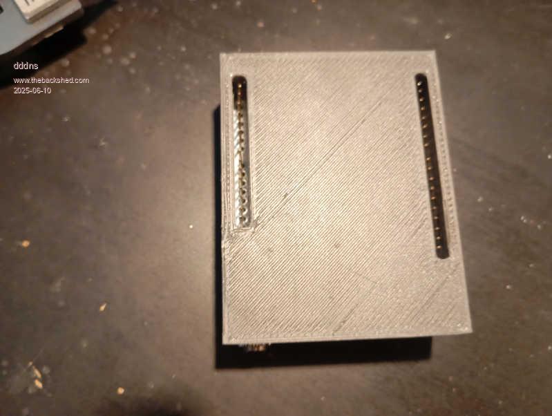 And this material for covering, it's PET and does not break. It can be cut with scissors or a cutter knife:  |
||||||
The path is the goal :) My last idea for a sense making "docking" solution. A chinese power source with 5 and 3V for two 18650 and a breadboard (ssd for size comparison): 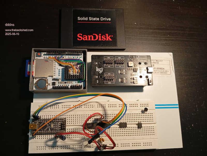 |
||||||
Hello :) Today sun is shining and I'm not so motivated. But carpe diem and I designed an inlay: 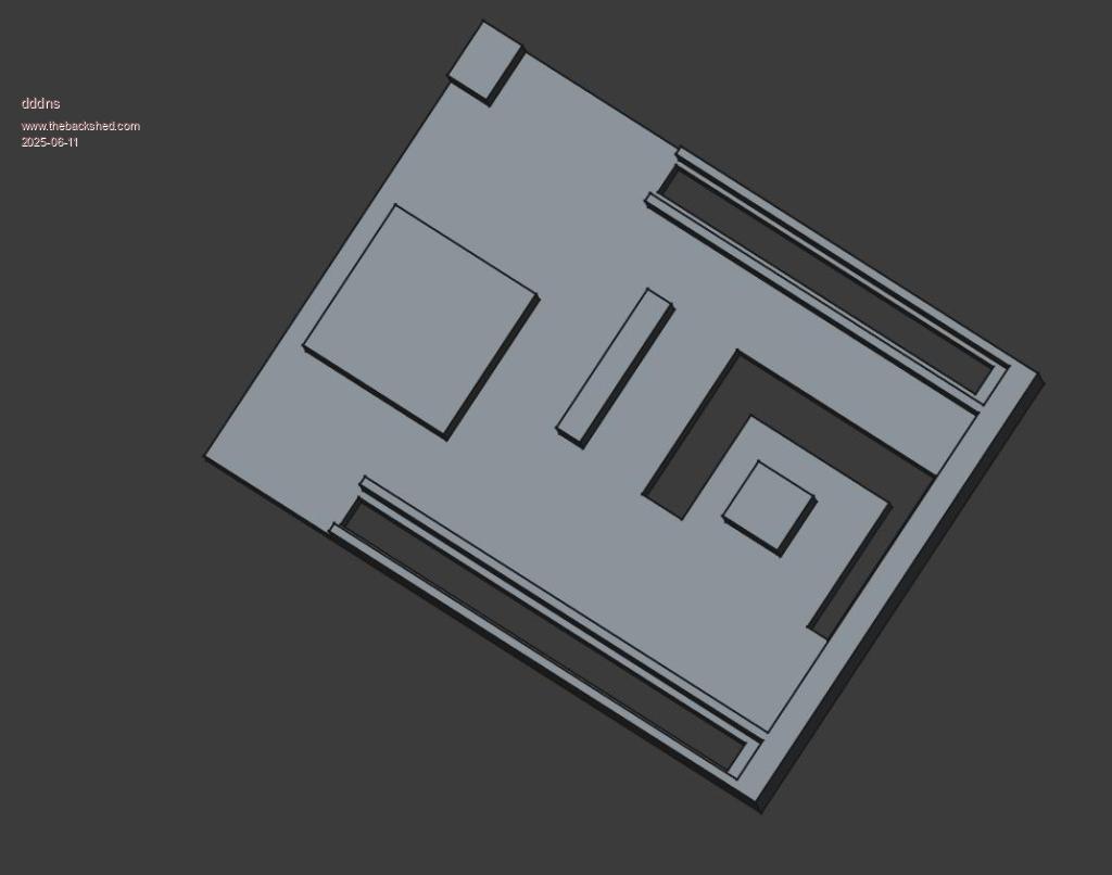 Again, cleaned it with the little mill: 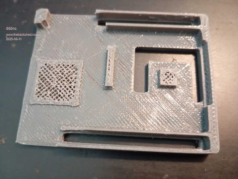 and fitted it in. Another pocket of around 1mm is created: 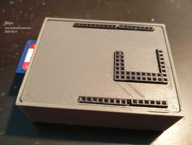 The inlay is 7mm in heigth: 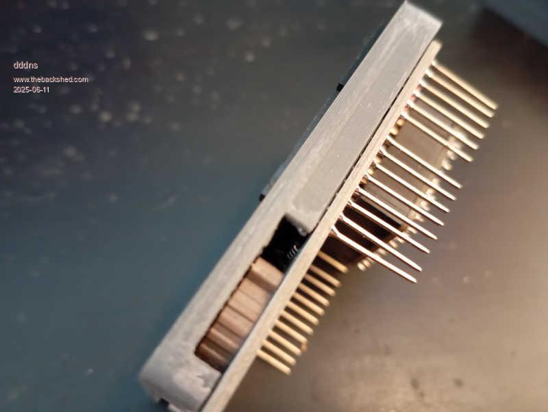 |
||||||
Good evening! I need to get this done now..enough is enough of tinkering now. I would like to look into HDMI so I clenched my teeth. First the PET: 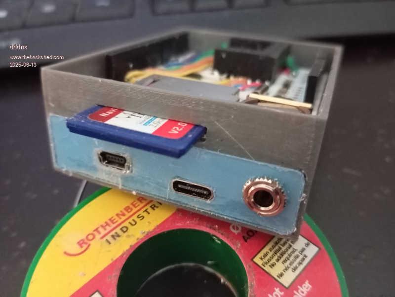 Then the inner wiring and on the board: 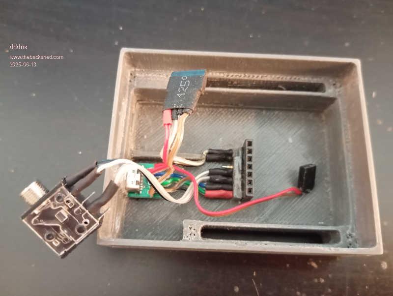 Finished so far, maybe I will move GP1(SD CS) to GP10 later: 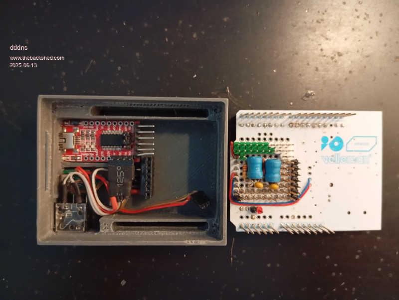 Multilayer :)) 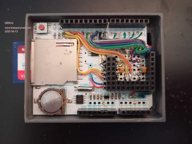 |
||||||
Hello All :) I've exported the inlay from Freecad as .svg to Inkscape. Now it's easy just to position the labeling around. Only need to setup a linefeed of 2,54mm and just write it down on each row. Then I printed the first drafts on white paper and made sure everything fits. For the cutting and tho whole process I used nothing but: 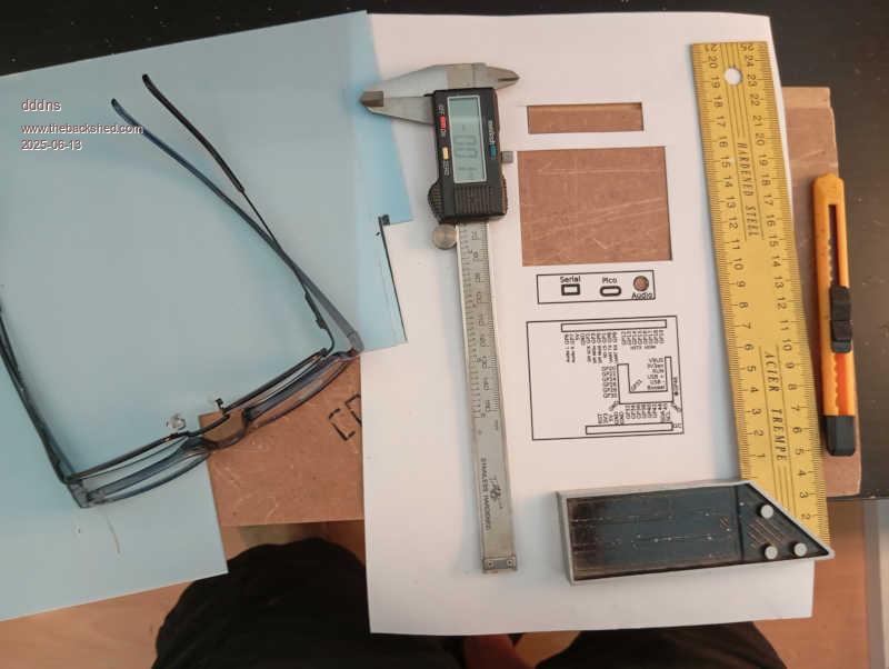 And two hours of concentration and patience: 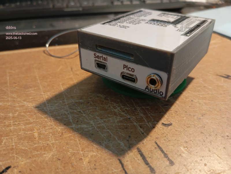 In this very close up it looks so lala, but in reality you don't see much of it: 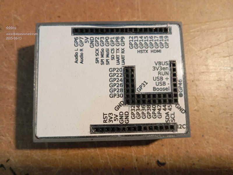 |
||||||
| The Back Shed's forum code is written, and hosted, in Australia. |
