| Menu | JAQForum Ver 19.10.27 |
| Menu | JAQForum Ver 19.10.27 |
Forum Index : Microcontroller and PC projects : PicoMite V6.00.02
> option list PicoMiteHDMI MMBasic USB RP2350A Edition V6.00.02 OPTION SERIAL CONSOLE COM2,GP20,GP21 OPTION FLASH SIZE 4194304 OPTION COLOURCODE ON OPTION KEYBOARD US OPTION RESOLUTION 640x480 @ 252000KHz > > update firmware Error : Unknown command > |
||||||
See note is manual for UPDATE FIRMWARE [NOT ON USB VERSIONS] |
||||||
Ok, thanks I missed that. |
||||||
Subs, pages 160-161 1. Seems Duplicated paragrapgh. 2. Seems Duplicated but edited. If duplications removed, TEMPR START would not be split across pages 161-162 as it is difficult to follow read. 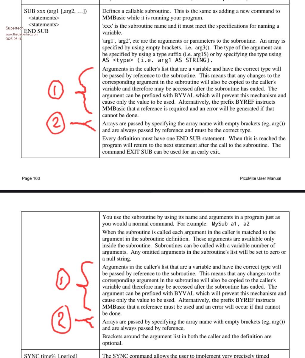 Regards. |
||||||
Page 76, as still in all Webmite manuals to date, THEN this is still missing a couple of them.....hint, hint... 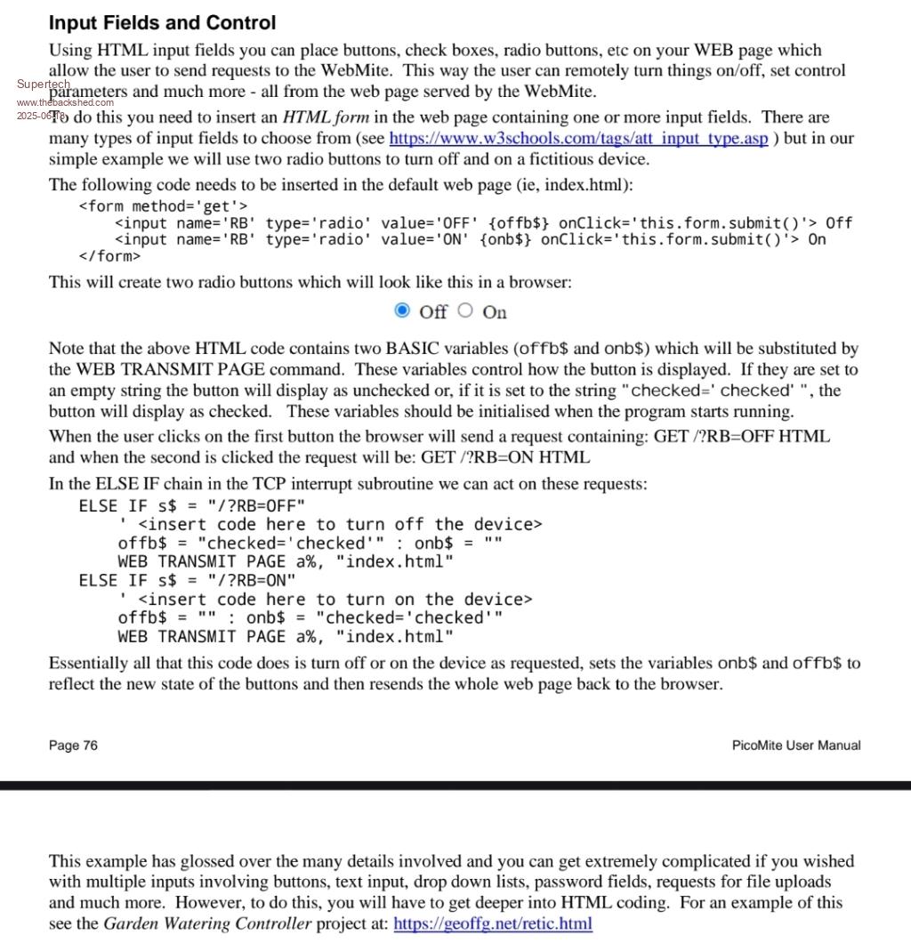 Regards. |
||||||
@Peter, Geoff, thank you for this release. Marcel |
||||||
@Peter, Geoff, thanks for this release. So far everything works fine. One problem I ran into was the disruption of the I2C bus because I use old Arduino hardware like LCD displays 4x20 with an I2C module and no pullup resistors! Mount the pullup resistors directly to the GP pins to 3V3. It turns out that the current bus speed is too high for these modules. (400KHz) So I lowered the speed to 100KHz and it works fine so far. OPTION SYSTEM I2C SDApin, SCLpin, SLOW Greetings, Jan. |
||||||
I'm pretty new to the PicoMite and have just built out a VGA/USB system on breadboards. I have to say I'm loving it and thank you for the new firmware. Some nice improvements! Question: where do I get the "help.txt" file for the help command to work and what do I do with it? Thanks. ...mathom... |
||||||
Hi mathom, I think ths is the latest version (2025/04/19): https://www.thebackshed.com/forum/ViewTopic.php?TID=17777&PID=237581#237581 |
||||||
Got it! Thank you! |
||||||
Got it! Thank you! |
||||||
if you want something more solid than your breadboard solution, I recommend the PicoMiteVGA Construction Pack: https://geoffg.net/Downloads/picomite/PicoMiteVGA_Construction_Pack.zip 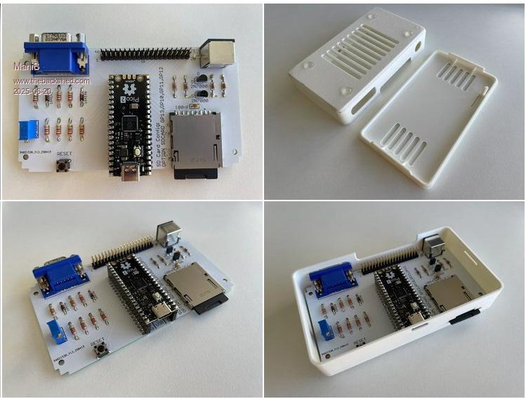 |
||||||
Hi ManiB, Yes, that is the grand-dad of all the stand alone pico basic computers. There is also a VGA design 2, where audio is added, and the optional RTC (and breadboarding footprints). I started, and still love, VGA design 2. 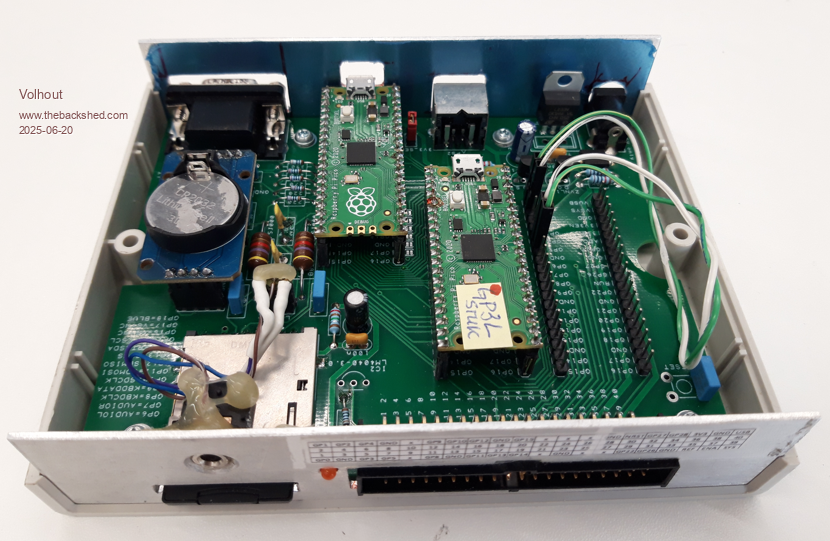 In this photo a breadboard footprint is used for a second pico, that runs a chess program. The main pico is for display of the chess board, and keyboard interface. The "breadboard sockets" are very nice for playing with interfaces (like the SSTV interface, the MORSE interface, etc...). Note that VGA design 2 is just an extended VGA design 1. Just RTC and Audio added (and the breadboard footprints). If you desire to retro-fit audio and RTC in VGA design 1 added later on, Peter made a piggy-back board for that, I think the design files are on this forum. Volhout Edited 2025-06-20 16:33 by Volhout |
||||||
Yes Volhout, i know ;) and this is the latest refernce board from Peter: 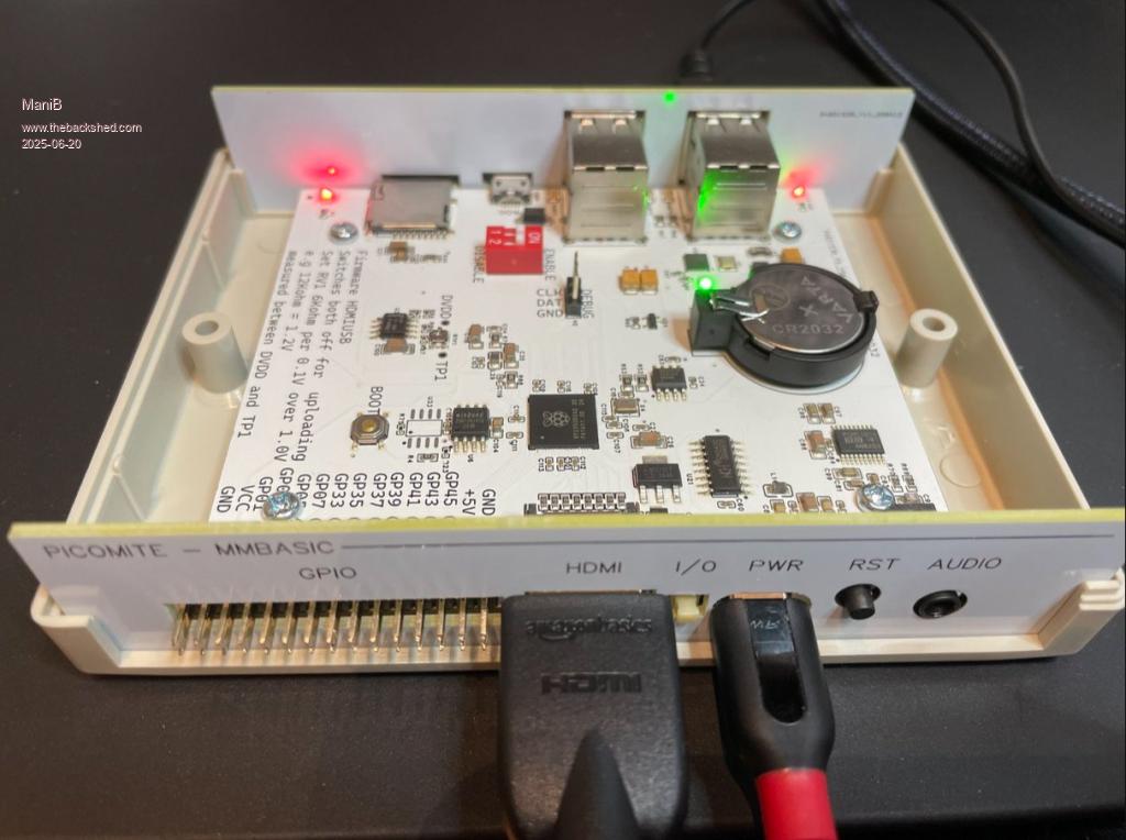 |
||||||
Does anyone have any spare of these boards (and panels??) available, and willing to ship to an Aussie? |
||||||
Maybe try a PM to Grogster. John |
||||||
Where are the details for this ?. I'd love something full featured that can fit in a small case with keyboard and touch screen plus lots of free i/o, space for several additional modules, holes for mounting a heatsink on the processor and dual 18650 batteries ! |
||||||
Here: https://www.thebackshed.com/forum/ViewTopic.php?TID=17301&P=11#236097 And here: https://geoffg.net/picomitevga.html Edited 2025-06-22 06:16 by ManiB |
||||||
@Peter, I am sorry to report a bug in 6.00.02 release. This is tested on PWM audio on 6.00.02 on the VGA design 2 platform, but could very well be transparent over multiple platforms. In my effort to display Lissajous graph, I tried this: PLAY SOUND 1,L,S,1000,25 PLAY SOUND 2,R,S,1001,25 DO : LOOP The left channel shows a sine wave centered around 1.65V, frequency 1kHz. The right channel does not show a sine wave centered around 1.65V, it switches to 3.3V dc. Even when I comment out the L channel, the right channel outputs DC. Volhout |
||||||
Same result on basic Pico 1. Though PLAY TONE 1000,1001 does work on the same pins. |
||||||
| The Back Shed's forum code is written, and hosted, in Australia. |

