Posted: 11:38pm 10 Sep 2025 Copy link to clipboard
Chrisk Senior Member
I tried the initial wiring from the FTDI site as ElectroPI suggested. That didn't work so then I tried the wiring from the picaxe manual, that too didn't work. I also tried using another Picaxe08M chip thinking it might be the problem and that still didn't get it working
I now have measured measured the voltages at the 3.5mm audio plug and I get 5V at the tip WRT the sleeve.
I then sent the program, and found it went Low for a duration and then back to High. This seems to agree with what Phil99 says how it should work but unfortunately it's still not working. I will continue to battle on until we all get an answer.
What should the COM speed for communication be?. I have it set to 9600.
Posted: 12:35am 11 Sep 2025 Copy link to clipboard
phil99 Guru
Ok so the sleeve is ground and the tip is probably Tx and the ring Rx, as indicated by @ElectroPI. Previously I mentioned cutting the cable to swap the wires but if this is on a breadboard swapping the connections on the breadboard would be better. So that is standard TTL Serial but the PICAXE requires Inverted TTL Serial. @ElectroPI also showed it may be possible to re-program the FTDI to deliver inverted TTL. If that doesn't work inverting the signals with hardware will. In my previous post I setup a MicroMite to use Inverted TTL and proved the transistor inverters will work. You could also use logic chips as previously mentioned. Use whatever you have in the toybox.
Re baudrate - from PICAXE website:- For most chips the default power-up operating frequency is 4MHz so I think you need 4800 baud. For X2 chips use 9600 baud.
Edit. You can test the FTDI by linking Tx (tip) to Rx (sleeve) then anything you type in TeraTerm should be echoed back to the screen. Edited 2025-09-11 15:49 by phil99
Footnote added 2025-09-11 20:45 by phil99 A mistake Should be "You can test the FTDI by linking Tx (tip) to Rx (ring) "
Posted: 06:19am 11 Sep 2025 Copy link to clipboard
mozzie Senior Member
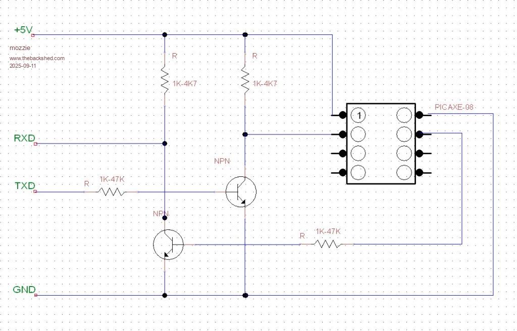
G'day Chris, Good news I hope I have tested the circuit desribed by Phil99 on a Picaxe08 and it works with a generic TTL232 lead
Hopefully you have a couple of generic NPN transistors and 4 resistors in a bitsa box somewhere, and you figured out which connection is which on your lead.
TXD = TX data from the converter cable, ditto for RXD = RX into the converter cable. Good Luck
Regards, Lyle.
Posted: 01:34am 12 Sep 2025 Copy link to clipboard
Chrisk Senior Member
Hi All I tried putting inverters in the Rx and Tx lines and the message I got from the program wa that it couldn't find the device. I am taking a trip to visit Mossie so hopefully an answer will soon arrive.
Posted: 01:51am 12 Sep 2025 Copy link to clipboard
phil99 Guru
You can test the FTDI cable by unplugging it from the PICAXE and linking Tx (tip) to Rx (ring) then anything you type in TeraTerm should be echoed back to the screen, no matter what baud rate or signal polarity is used. . Edited 2025-09-12 11:56 by phil99