
| Menu | JAQForum Ver 26.09 |
| Menu | JAQForum Ver 26.09 |
Forum Index : Microcontroller and PC projects : Problem with Olimex RP2040 PC and COM2
  Page 2 of 4   |
||||||
> option list PicoMiteHDMI MMBasic RP2350A Edition V7.00.00RC9 OPTION FLASH SIZE 4194304 OPTION COLOURCODE ON OPTION KEYBOARD US OPTION RESOLUTION 640x480 @ 315000KHz OPTION HDMI PINS 1, 3, 7, 5 OPTION SDCARD GP22, GP6, GP7, GP4 > I've only enabled HDMI and the SD card - otherwise, everything is set to the default settings. The hardware remains unchanged. I'm using COM2 via the UEXT port. UEXT is connected to pin 26/27 (GP20/21) and I'm using an original Pico 2 with an RP2350. I think the pins aren't configured correctly when the system restarts. They're actually supposed to be in tristate mode. Frank Edited 2026-11-15 16:44 by Frank N. Furter |
||||||
The correct idle state for TTL serial is high. The idle state for RS232 is low. The MAX3232 is a RS232 chip so I would expect it to pull the Rx pin of the Pico low, unless you put a pull-down resistor on the T_IN pin of the MAX3232. 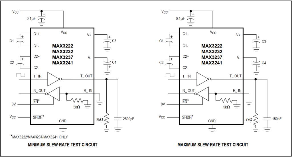 Edited 2026-11-15 17:15 by phil99 |
||||||
At this point, the serial port hasn't even been initialized yet! The Pico is blocking communication. I may not have made myself clear: I turn on the system and the LED lights up WITHOUT the interface having been activated. I can start my program and it runs - but the HX-20 terminates the connection due to a communication error. That’s no surprise, since the line is permanently connected to GND and no communication is possible. When I launch the file manager, the LED goes out. When I then launch my program, I see both LEDs flickering, and communication works. By the way, the LED lights up even WITHOUT an HX-20 connected. It's the Pico that pulls the line low. Only after the file manager has been launched will the signal levels be as they should be. Take two LEDs, each with a 1K series resistor connected to 3V3, and connect them to GP20 and GP21. You'll see that one of the two LEDs starts glowing immediately after powering on, WITHOUT you having run any program. Frank |
||||||
Going back to the beginning... Have you had the HX-20 working with the genuine RS-232 port on anything else? Does it need hardware handshaking linking out if you are only using RXD ans TXD? Does it work if you do a simple loopback on RXD-TXD? There's no point in attempting to connect it to the Olimex unless you can prove that it's working. Even if it is, MMBasic doesn't support any handshaking so you will need to sort that out in your software and/or hardware. |
||||||
@Mick: It actually works with the “Olimex RP2040 PC” board!!! But ONLY if I've launched the file manager first! No matter what I do, the LED on the GP21 stays on until I launch the file manager. > setpin gp21, din > setpin gp20, din > setpin gp20, dout > setpin gp21, dout > pin(gp20)=0 > pin(gp21)=0 > setpin gp20, din > setpin gp21, din What makes the file manager different? However, when I set GP21 as an output and set it to “High,” the LED dims. That would actually suggest that the MAX3232 is pulling the output low. But then why are both LEDs off when the file manager is launched? And why does communication with the HX-20 work then? Frank |
||||||
Good question! I wonder if it's something to do with the file manager being a command line application, not a running program? It's putting something into a known state prior to RUN? |
||||||
In any case, I haven't yet found a way to achieve this in any other way. I'd like to run my program in autostart mode. Unfortunately, that's not possible right now, since I have to launch the file manager first every time. This is an emulation of the Epson Video Adapter (EVA), which allows text and graphics to be displayed on a monitor via the PicoMite. The program works if both LEDs are off before startup. However, that’s only the case after the file manager has started... Frank |
||||||
Manual: This makes me think... RS-232 is also idle high. I would assume, then, that you need level shifting, not inverting RS-232 converters. A single mosfet level shifter in each direction like this should be ok. |
||||||
G'day Frank, Thanks for the Option List, this helps us to simulate your system, although the symptoms you describe are puzzling to say the least. It might be worth checking there is not a short between GP21 and GP22 on the board, this is the SDCard CS pin and the File Manager might toggle this when opened. Also, whilst the pins are neither input nor output on power-up, the pull-down resistors are enabled, if you are using high brightness LED's this will cause them to glow: > ? bin$(peek(word &h40038054),32) ' RP2350 pin control GP20 00000000000000000000000000010110 ' Pull Down Enabled > ? bin$(peek(word &h40038058),32) ' RP2350 pin control GP21 00000000000000000000000000010110 ' Pull Down Enabled > The MAX3232 is an INVERTING driver, so with GP20 as the TX to your MAX3232, with GP20 low the MAX3232 ouput will be high and this may affect your device. A pull-up resistor will put in the correct idle state until your program takes over. The silicon fault in the RP2350 could also be an aspect, try 4k7 as a test. Pin GP21 is the RX pin so should be driven from your MAX3232, this should also idle high. Is the GND connection between the 2 devices definitely connected? As Mick and I suggest, a loopback test with the program posted earlier will at least prove the PicoMite is working correctly. Further thought required. Regards, Lyle. EDIT: I recommend to try the PULL-UP resistor on GP20, this should solve the problem. Edited 2026-11-15 20:16 by mozzie |
||||||
Resistor level shifting without inverting was suggested at the beginning. However as RP2350s are 5V tolerant, provided the HX-20 is fed from the same 5V supply as the regulator for the Pico, no level shifting is needed. just connect Tx to Rx and Rx to Tx. |
||||||
G'day Phil99, Is the serial port on the HX20 TTL232 at 5 volts or RS232 at +/- 12Volts? Franks use of a MAX3232 would suggest RS232 but I am not familiar with this unit. Might explain why it won't work. Regards, Lyle. |
||||||
That's *if* the HX-20 uses TTL levels. It's old enough to have proper RS-232 using 0V and 12V levels, especially as it was intended to drive printers and modems. Personally, I'm suspicious of "5V tolerant" on inputs that are no such thing if the Pico loses power for any reason. You need pretty big series resistors to protect the diodes (which aren't rated for continuous dissipation) and that, in turn, compromises the voltage levels. MOSFETs don't cost much more than resistors now. :) |
||||||
Did a search for "HX-20" and found Epson HX-20 Calculator. It appears to have a 5V TTL serial port and a +/-8V RS-232 port for a telephone coupler. It has a dot-matrix printer that uses 5V TTL serial. More information from Frank would help. |
||||||
This is what I first thought of: HX-20 |
||||||
Found it! From here So, for compatibility with a Pico, you may need inverters followed by a MAX converter. ---------------------- Also very interesting: serial port transfer . Edited 2026-11-15 21:29 by Mixtel90 |
||||||
The MAX3232 has +12V and -12V charge pump converters built in. . Edited 2026-11-15 21:30 by phil99 |
||||||
RS-232 specifies from +/-3V to +/-25V. There's nothing like being flexible. :) |
||||||
Unfortunately not all equipment adheres rigidly to that specification. The original IBM PC required a minimum of +/-10V, and not a mV less! I built a kit modem for one that only produced +/-9.5V. After figuring out why it wouldn't work managed to modify it to get +/-12V. |
||||||
There once was a clever circuit for RS232-to-TTL conversion that was used in several projects (I believe it was also featured in the 8052AH-BASIC computer project, for instance) and requires neither an IC nor a negative voltage supply: 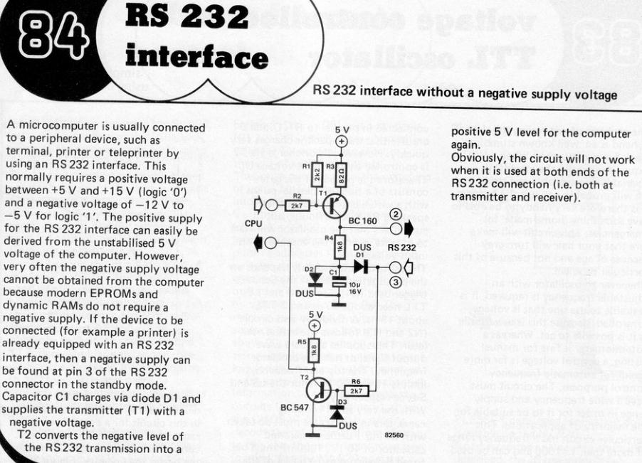 It derives the necessary negative voltage from the idle state of the remote device’s Tx line via the Rx line. It can certainly be easily adapted for microcontrollers that operate on a 3.3V supply; in that case, the voltage at R5 (for transistor T2) should simply be 3.3V. However, the voltage at R1 and R3 (for transistor T1) should be at least 5V, given that the RS232 signal threshold for the Rx line is >= ±3V. This voltage at R1 and R3 poses no issues for 3.3V microcontrollers. Incidentally, the entire issue (a collection of circuits from July/August 1982, "1982-07_08.pdf") can be found here: https://archive.org/download/ElektorMagazine/Elektor%5Bnonlinear.ir%5D%201982-07_08.pdf Regards |
||||||
Oh yes - I remember that! :) If connecting to a RP2350 it's essential that the 5V supply comes from there. The CPU pins do get 5V on them, albeit current limited by R2 and R5. I'd be tempted to increase R5 to 2K7 for this reason. Not a good idea to connect it to a RP2040. |
||||||
| Page 2 of 4 |
||||||
 |
The Back Shed's forum code is written, and hosted, in Australia. |


