| Menu | JAQForum Ver 19.10.27 |
| Menu | JAQForum Ver 19.10.27 |
Forum Index : Microcontroller and PC projects : Stepper Project
The reason that I prefer capacitive touch is that they are resilient. I have been using MicroTouch (now 3M) since the eighties and the only reason they have ever been replaced is due to a dead CRT. This is a Samsung TAB 2 that has been abused since 2015. It responds perfectly in spite of the mess. They can't even be bothered to wipe it down. 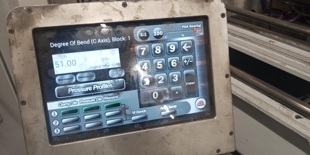 |
||||||
Phenix, I do like the style and color of that UI. Might be a nice exercise to port that on a pico. You would need a higher resolution screen though, 320x240 wont do. But 640x480 would. No need for framebuffers, just blit elements to screen. Volhout Edited 2026-06-02 04:18 by Volhout |
||||||
Hi Harm, So I have matherp reading my mind re: PicoMite developments and now you are reading my mind re: GUI  Yes, I'm thinking 640x480 and I have already been playing with blit  CoolText Button Factory |
||||||
On a 7" SSD1963 this could look exactly the same, non glare though but with nice touch ability. Blit would be very fast almost like HDMI |
||||||
Just to say thanks to Mozzie, in answer to my question.. "It looks like if you issue STEPPER RUN while its already running it gets upset and stops." As you say, using this line fixes it. If Peek(stepper active)<>-1 Then Stepper close You nailed it!  |
||||||
Well still on my morning caffine intake and Lyle that new screen for the setup axis does look nice Anyway I checked the shipping for my LCD boards and Aussie post hasn't updated since last Thursday saying it's stuck in Melb  all approved but no updates. all approved but no updates.Just thinking about the GUI numberbox it has been around for donkeys years and now the stepper code is nice and stable could I be bold enough to ask for a decimal point to be included in the number box which would simplify putting small cuts on in the stepper system. I'm sure many will agree as the GUI has now grown onto VGA/HDMI having this option to go lower than 1 will serve many members besides myself. Now I did put in my setup code Enable is GP0 on the Z axis and the enable is hard wired to the X and Y axis. Now when I start the code the stepper system stays in idle mode as indicated by my programmable power supply. When I take off the dupont connector for the enable the stepper system comes active. Now a few times I have found after doing a few tests the power supply drops to 8 volts and the 1.8amp max current is reached also the red light on the power supply is indicating the error. Do a reboot leaving the dupont enable disconnected and all is well then many times the touch stops working so I did a GUI test touch until it does respond. Doing a Stepper Status on the command line does work great now as the stepper system works in the background it would be nice if the commandline updates the stepper system which would go along way to debugging the code. Being able to see what is going on would go a long way with new users like myself and many others.Now a task I need to do is load up the buffer with code so an explanation on how this can be done will be nice. Regards Bryan |
||||||
G'day Bryan, To load G-Code into the buffer you can type it at the command prompt as long as the stepper system is active in the background (run the program and then exit), there are 3 options: STEPPER GC G1 X100 F100 STEPPER GCODE G1,X,100,F,100 STEPPER GS "G1 X100 F100" OR A$="G1 X100 F100" STEPPER GS A$ This line from the original program does this: Stepper GCODE G1,X,Peek(stepper X)+CtrlVal(XPOS),f,CtrlVal(XFPOS) When you hit the JOG buttons. The NUMBERBOX works with floating point, the decimal point is on the second page, hit the ALT key (bottom left) on the keypad and you'll find it. The ENABLE for the steppers was deliberatly setup to disable the drivers when the system is not working, you can change this by changing the STEPPER INIT line to: STEPPER INIT 0.05,150,GP22,1 So when you run the program the steppers will stay enabled (I hope) Regards, Lyle. |
||||||
G'day Phenix, That is one slick looking HMI I too hope we can do similar with a PicoMite soon. Regards, Lyle. |
||||||
Hi Bryan, If you want to enter G-Code at the prompt you will need to comment out STEPPER CLOSE from the program first. Now back to work.... Regards, Lyle. Edit: both programs need "STEPPER CLOSE" commented out. Edited 2026-06-02 13:24 by mozzie |
||||||
Well after 10 minutes of playing with this today those pesky inference lines started again and on just checking the tracking those LCD boards should be here on Friday So hopefully that interference will be gone for good.Lyle I can include 2 off 3V3 and one 5V S09 regulators for you and 2 off pcb's of both boards so you can have a play. Now I did find the RTC won't connect and reading in the manual 100K internal pullups are used but I may just put some pullups on to see if that cures the problem. After all this bad weather got some roof repairs to do when it finally stops raining Regards Bryan |
||||||
G'day Bryan, With all the testing and messing around done here the 4" ST7796S display has been rock solid, not seen any of the issues you are seeing so hopefully fitting the LCD to a PCB will solve the problem. Having said that the coil winder is fitted with a ILI9488 so it is the real world test. Looking forwards to those boards, I just scored a tiny CNC milling machine from a mate so guess what the first test will be on  Regards, Lyle. |
||||||
Hi Bryan, Just looking back over some things and couldn't figure out why the steppers won't enable. This might be a problem: 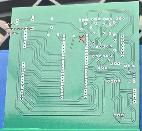 I think this has the Enable permanently tied to 3v3. Hopefully an easy fix Regards, Lyle. |
||||||
Well those LCD boards turned up this morning So Lyle I will get that post of the boards off today as I need to go into town and buy a usb hub so I can setup my laptop as my house computer as the current one has a trojan which is reacking havoc and just trying to bring google is a no go.I did download Trent Micro House Call virus checker and on every run it finds the same trojan so that win10 box is going to my daughters boyfriend who is the IT guru to sort out. This morning got onto Ali to get some DS18B20's then it clicked as I do need to put my new visa card numbers to leave it until I'm on this shed computer Anyway got a few jobbies to get out of the way before I get a chance to get back on this Surface Grinder project as all the rewiring does need to be done before any testing can be done. Regards Bryan |
||||||
Ok finally found some time to get back on this project and I've soldered up the lcd board but can't get the lcd to work. Now when I type in backlight 2 the display does dim but trying to do the bubble test I'm just getting static on my shed radio and the lcd isn't showing the bubbles. So I did try the ST7796SP one as the ST7796S didn't work and it's still the same. Now I have traced every connection and found no errors in the wiring. PicoMite MMBasic RP2350A V6.03.00RC14 OPTION SYSTEM SPI GP18,GP19,GP16 OPTION SYSTEM I2C GP10,GP11 OPTION FLASH SIZE 4194304 OPTION COLOURCODE ON OPTION CPUSPEED (KHz) 200000 OPTION LCDPANEL CONSOLE OPTION DISPLAY 26, 40 OPTION LCDPANEL ST7796SP, LANDSCAPE,GP15,GP14,GP13,GP20 OPTION TOUCH GP12,GP17 OPTION SDCARD GP21 Now when I first tried I typed run and the stepper system did arm and with the enable connected it did stay unarmed so the board is OK. I did think it could of been that old AAA 4 cell case as it old and rusted a tad so swapped it out with a 10 volt DC in plug pack but still no change. Got 5V on the 5 pins too so not sure what is going on here. Regards Bryan |
||||||
G'day Bryan, Good to see you making progress, I have been munted by the flue (or something) for the last week, very nasty  A close look at the LCD PCB and it looks like: MISO is connected to Touch-DIN MOSI is connected to Touch-DOUT 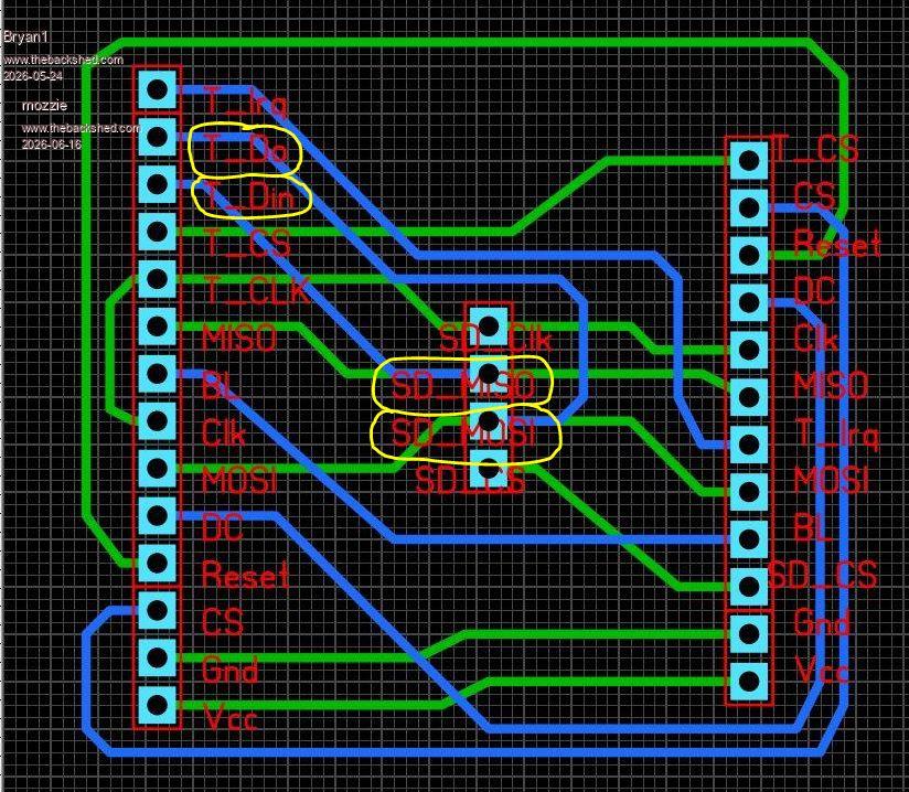 This could be causing some grief  Regards, Lyle. |
||||||
Thanks for pointing out that mistake I made Lyle I changed the SDCard 4 pin header to a 90 degree pin setup and put it under the pcb then cut both tracks and soldered in jumper wires the correct way. I did put V3.00RC19 on and doing B: files did show the SDCard contents but trying to set the time on the RTC is still going the "not found" error. Now as the boards only cost $3.50 for 5 of them I'm going to get on and correct the error of the SPI lines which should make a nice no bones backpack for the LCD's.Regards Bryan |
||||||
Perhaps wait till the RTC issue is found and fixed, just in case that is a track problem too. Edit. I think you have SDA and SCL crossed over looking at the PCB here. I2C2 SDA should go to GP10 I2C2 SDA should go to GP11 Edited 2026-06-16 14:12 by phil99 Footnote added 2026-06-16 15:25 by phil99 Silly typo. should be:- I2C2 SDA should go to GP10 I2C2 SCL should go to GP11 |
||||||
Phill the PCB I meant is shown above and with the main stepper board Lyle has a couple of them so after he has tested them revisions can be made. |
||||||
The 3 I2C sockets are wired correctly to each other but are the wrong way round at GP10 = I2C2 SDA & GP11 = I2C2 SCL. If you consider getting new boards made perhaps add a ground pin to the bottom socket. While you are at it there appears to be room for pads for pullup resistors on SDA and SCL. You may never need to install the resistors but it costs nothing to add the pads, just in case. |
||||||
Ok it does seem these grey cells got both boards all wrong so just got on and ammended the mistakes on both boards. Now with the LCD board moved the silk screen for the SDCard connector so one can see them and swapped over the SPI lines. On the stepper board corrected the I2C lines, put in pullups also put GP1 which is the Enable pin to ground as tying it to Vcc stopped the steppers being armed. Also with the step and limit connectors added a non connecting pin to make them a 8 pin socket as 7 pins sockets aern't around. Also one thing I need to do with every board which I neglected to do was put in mounting holes so they were added. V2 Stepper Board 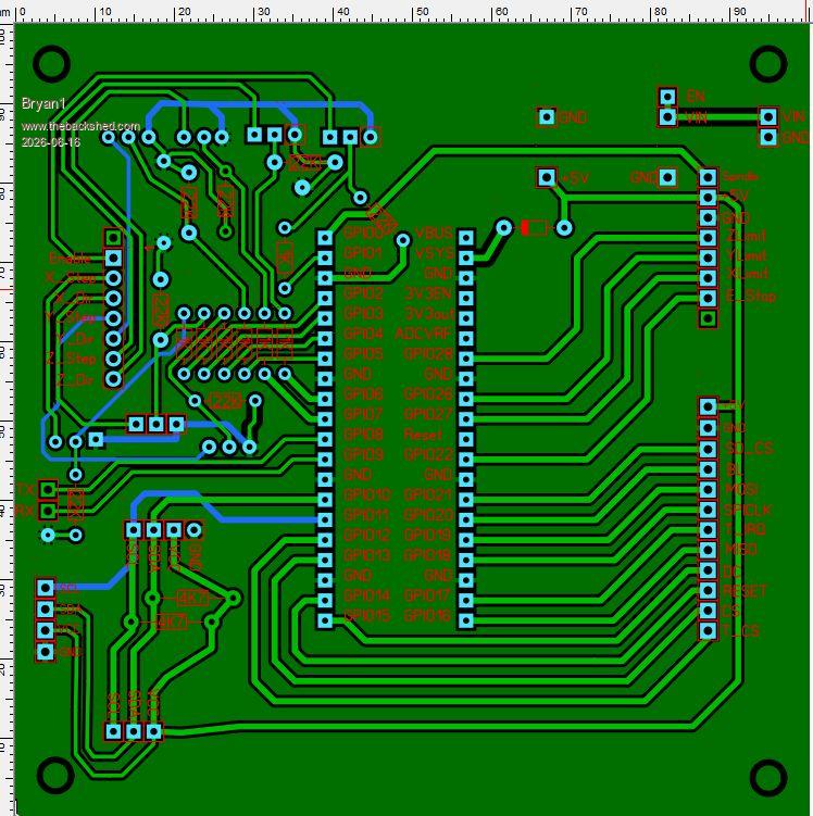 V2 LCD Board 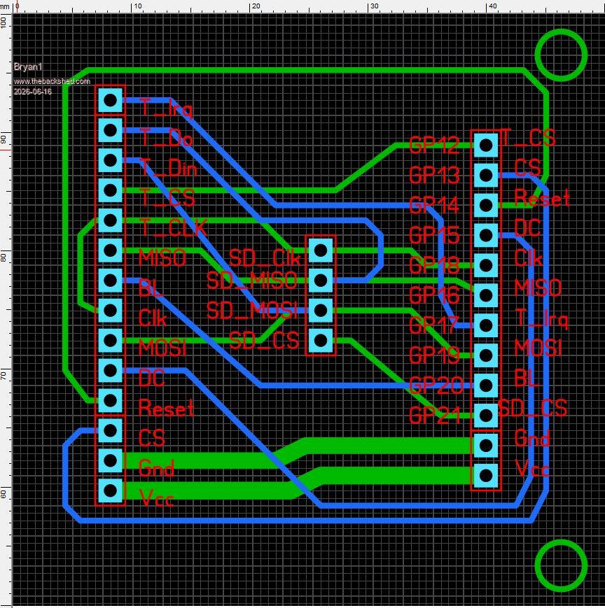 Now rather than rush ahead and order these boards if I have gotten something wrong again could it be pointed out please. Regards Bryan |
||||||
| The Back Shed's forum code is written, and hosted, in Australia. |

