Posted: 10:02pm 09 Mar 2026 Copy link to clipboard
tinyt Guru
For me if one Mosfet or driver transistor blew or measured to be bad, I replace them all (24 Mosfets plus 4 transistor pairs) - learned from my earlier bad experience.
And if a plated thru hole barrel plating gets pulled from unsoldering, I make sure top and bottom copper layers for the thru hole are soldered to the pin (works only for 2-layer pcbs). Edited 2026-03-10 08:06 by tinyt
Posted: 11:05pm 09 Mar 2026 Copy link to clipboard
Bryan1 Guru
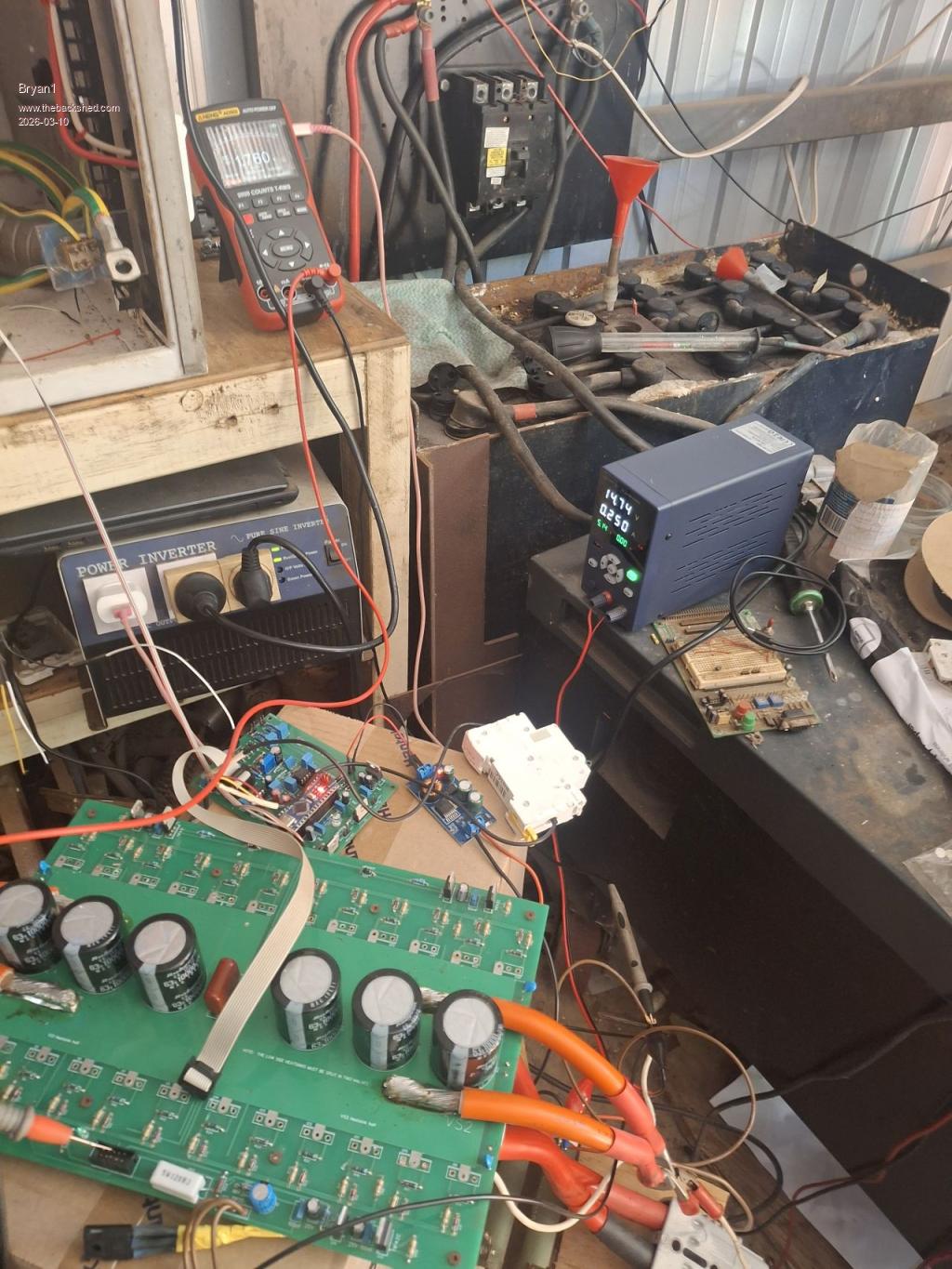
Ok with step 2. VS1 and VS2 tied to ground ribbon cable removed 24 volts and 320mA input turned on voltage on psu dropped to 20.34 volts and current draw 340mA.
TIP31 1.5 1.9 900mA
Measured the Vbat pins on the 10 pin connector 1.7 volts.
So there is something blown me thinks
Edit:
Tried again lowering the current to 250mA and the pictures shows the result Edited 2026-03-10 09:07 by Bryan1
Posted: 11:21pm 09 Mar 2026 Copy link to clipboard
Bryan1 Guru
Ok removed the VS1 and VS2 to gnd wires and the current dropped to 51mA connect Gnd to VS2 and the short happens. Remove short the led comes on and....
TIP31 17.93 VBat 17.5
D25 17.41 D26 17.44 17.72
18V zener 17.93
Edit: that was interesting powered it up and decided to measure the voltage on pin 1 of the TIP 41 and TIP 42 chips.
On VS1 and VS high side 17 volts On VS1 and VS2 low side no voltage. Edited 2026-03-10 09:39 by Bryan1
Posted: 12:14am 10 Mar 2026 Copy link to clipboard
Bryan1 Guru
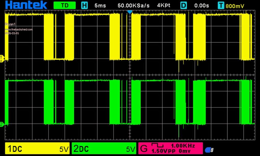
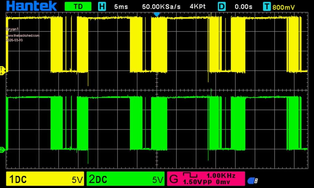
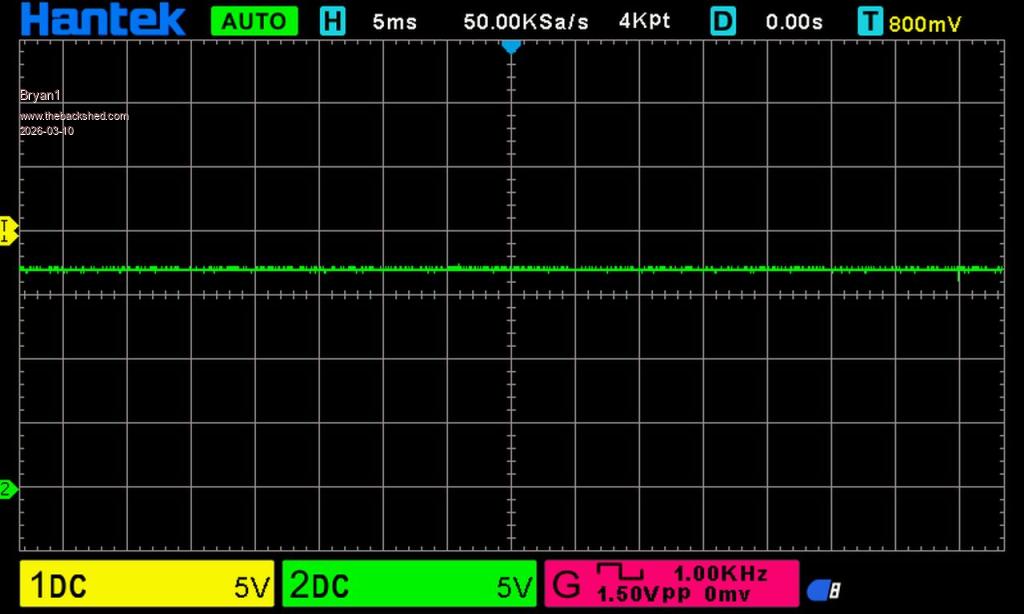
Ok the following scope pic's are WITHOUT VS1 and VS2 tied to ground
6. CH1 to R1 CH2 to D1
7. CH1 to R26 CH2 to D7
8. and 9.
CH1 R27 CH2 D18
so no action from the high side
Posted: 12:30am 10 Mar 2026 Copy link to clipboard
tinyt Guru
Looks like picoverter H01 and H02 signals are missing. So in the picoverter board, replace the two IR2184 chips and do steps 8 and 9 again.
Edit: I think the TIPs high side are shorted. are they newly replaced? If not replace them first before replacing the IR2184 as the shorted TIPs can blow the IR2184s. Edited 2026-03-10 10:39 by tinyt
Posted: 12:43am 10 Mar 2026 Copy link to clipboard
Bryan1 Guru
I did put new IR2184 chips in and when going to 8. the scope has seen the connection and just that flat signal on both channels now on 9. the scope doesn't even pick up a signal.
Anyway got an email this morning from Aussie post so those new chips should be here soon.
So finally off this project for a day or so and somehow waiting for Aussie post is a good feeling Edited 2026-03-10 10:45 by Bryan1
Posted: 11:00pm 10 Mar 2026 Copy link to clipboard
Bryan1 Guru
Ok checked the tracking this morning and just got the confirmation that package of TIP chips has arrived
So let the fun start again and see it I can get that energy meter to come to life.
Posted: 11:40pm 10 Mar 2026 Copy link to clipboard
Bryan1 Guru
Ok got the new TIP chips in hand so set up the tests again with the H01 and H02 TIP chips removed.
The short fault when VS1 and VS2 are connected to ground is still there.
So 24.1 volts 250mA current thru the resistor bank.
VS1 and VS 2 tied to Gnd
14.84 volts 250mA current
Remove VS1 and VS2 from Gnd
24.1 volts 46mA
Posted: 12:02am 11 Mar 2026 Copy link to clipboard
Bryan1 Guru
Ok removed the low side TIP chips and still got that short with VS1 and VS2 to gnd.
So with Vbat on 24 volts 46mA current draw decided to measure the mosfet solder joints and found something interesting.
H01 High side Gate 13 volts Drain VBat Source 13 volts
H02 High Side Gate 17 volts Drain VBat Source 17.44 volts
Edit:
Tied VS1 to Gnd turned it on and the TIP31 was at correct voltages now connect VS2 and turn it on VBat 2 volts 250mA current draw Edited 2026-03-11 10:17 by Bryan1
Posted: 01:10am 11 Mar 2026 Copy link to clipboard
tinyt Guru
check C8 for short or orientation. Also C21 for short. Edit2: Also C7 Edited 2026-03-11 11:14 by tinyt
Posted: 01:31am 11 Mar 2026 Copy link to clipboard
Bryan1 Guru
Removed from the board
Checked C8 93uf
Checked C21 94uf
Checked C7 104nf
turned it on let the caps charge then connected VS1 and VS2 to ground and short circuit as Vbat on 1.2 volts 250mA current draw psu showing 15 volts
Now it is VS2 where the fault lies as connecting VS1 does work. Edited 2026-03-11 11:32 by Bryan1
Posted: 01:33am 11 Mar 2026 Copy link to clipboard
tinyt Guru
Earlier you said VS1 to GND and TIP31 at correct voltage. except when VS2 is grounded Current draw is 250 mA. Is this still true?
Posted: 01:36am 11 Mar 2026 Copy link to clipboard
tinyt Guru
In the schematic the top row section, I think there is some short. We have to look for it.
Posted: 01:38am 11 Mar 2026 Copy link to clipboard
tinyt Guru
With no power, compare resistance reading at the pads of C8 and C5. Follow polarity mark on the silkscreen for the capacitors.
Posted: 01:39am 11 Mar 2026 Copy link to clipboard
Bryan1 Guru
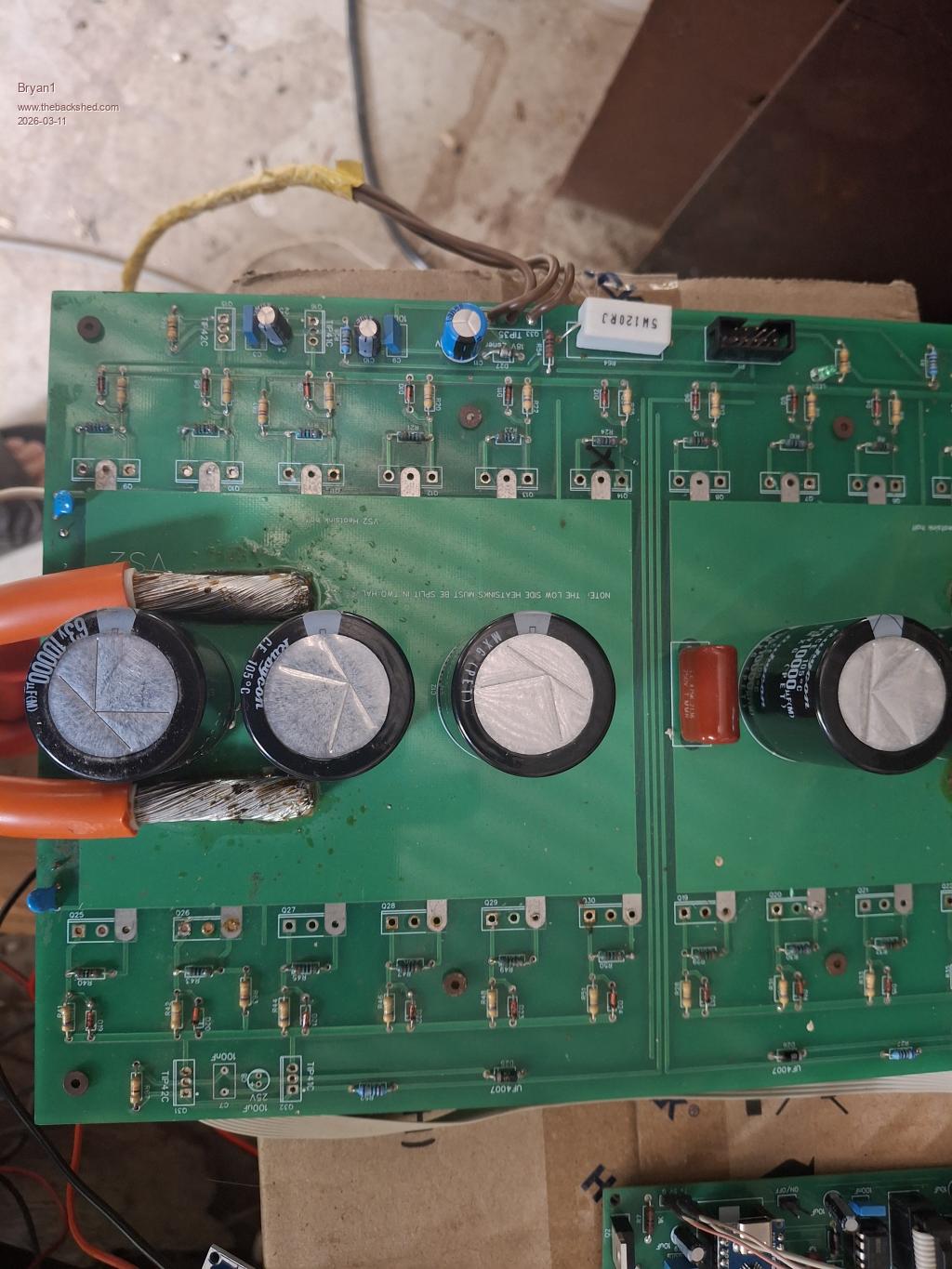
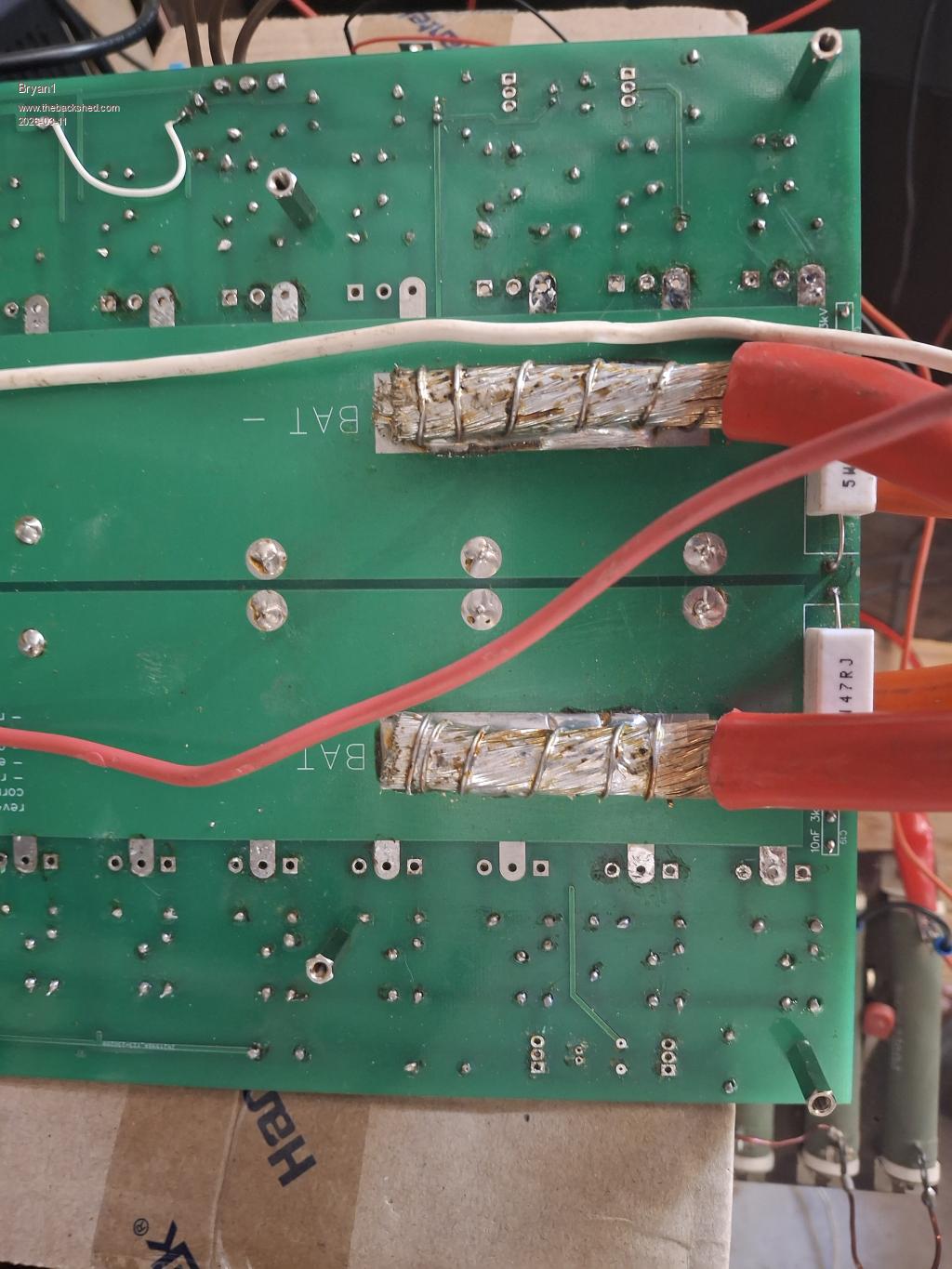
Ok got the linux box going now here are the pic's of VS2 on the board.
Top Side
Bottom Side
Posted: 01:55am 11 Mar 2026 Copy link to clipboard
tinyt Guru
Board is almost bare, and still we have a problem. Still with no power compare resistance readings across the pads of C8 and C5.
Posted: 02:00am 11 Mar 2026 Copy link to clipboard
Bryan1 Guru
C5 measured no measurement where C8 is a dead short, measured the 10K resistor which did prove to be 10K so left it in.
No probing using VBat - with one probe does NOT make contact around the C8 area with the other probe.
Checked VS with the VBat connections underneath and no contact so no shorts there. Edited 2026-03-11 12:14 by Bryan1
Posted: 02:04am 11 Mar 2026 Copy link to clipboard
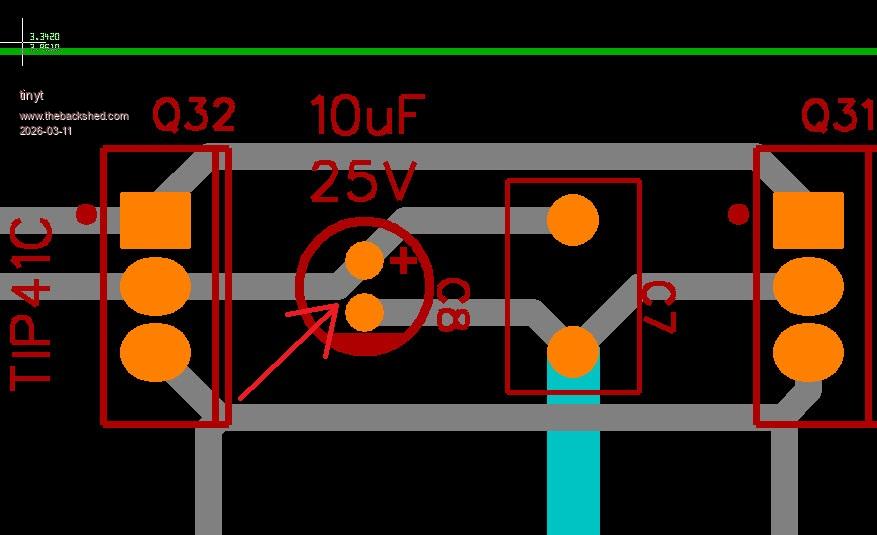
tinyt Guru
Use a magnifier and check for copper trace short between the pads of C8.
See red Arrow
Edited 2026-03-11 12:09 by tinyt
Posted: 02:22am 11 Mar 2026 Copy link to clipboard
Bryan1 Guru
Ok got a sharp knife and ran between the track and pad and the exposed copper does show the dead short. I also had a look with my 45X magnifier which does confirm the short.
So I am thinking cut the track from the TIP 41C to the cap and make the connection under the board using the cap legs to make the new circuit path. Edited 2026-03-11 12:25 by Bryan1
Posted: 02:33am 11 Mar 2026 Copy link to clipboard
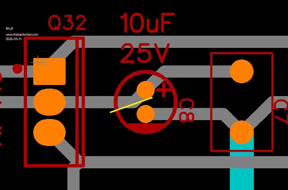
tinyt Guru
I would just cut a little bit of the shorting copper.
See yellow below, You can paint the exposed copper with a little bit of nail polish or something similar.
Edited 2026-03-11 12:36 by tinyt
Page 21 of 28
The Back Shed's forum code is written, and hosted, in Australia.