Posted: 03:56am 12 Mar 2026 Copy link to clipboard
tinyt Guru
IR2184 could possibly be damaged also. Check also the 20 ohm resistor. When you dremel'ed the shorted copper, I hope you left some copper, check for existing continuity between C8+ and Q32 middle pin. Edited 2026-03-12 14:01 by tinyt
Posted: 06:50am 12 Mar 2026 Copy link to clipboard
Bryan1 Guru
I ohm'd all those tracks and they all have continuity and replaced the H02 TIP chips set it all up again and back to a dead short now looks like I'm glad I got double the amount of TIP chips as they are all getting replaced in the morning as thats enough for one day.
Posted: 08:00am 12 Mar 2026 Copy link to clipboard
Bryan1 Guru
Ok I have to own up with that hack I did of putting in the jumper wire silly me soldered it to L01
So basically in the morning all the TIP chips will be replaced so I can get back to scoping the result and new mosfets will be installed as I do have 55 of those HY5608 mosfets and I should of put new ones in to start with.
Now I do have a blank power board I have been using as a reference and using my 45X microscope the C8 track is totally clear of the short circuit.
As the current power board does have 50sqmm for VS1 and VS2 and 65sqmm for the Vbat connection any and all hacks will be used to get this board going.
Posted: 01:24am 20 Mar 2026 Copy link to clipboard
Bryan1 Guru
Well had a bit of break from this inverter project and got back to it this morning, replaced 2 of the TIP chip sets leaving me one spare set
Anyway got it all sorted I think
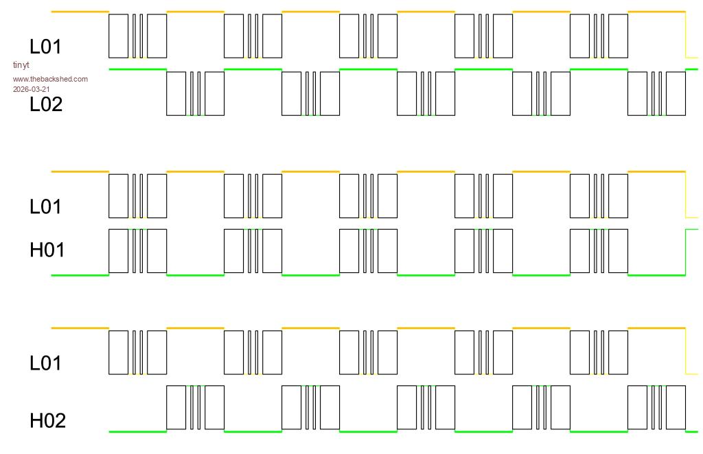
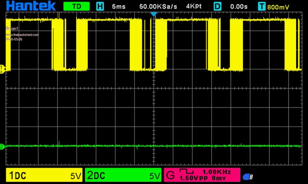
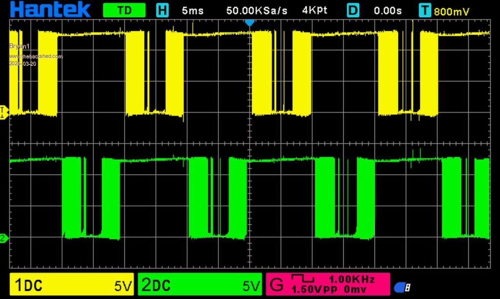
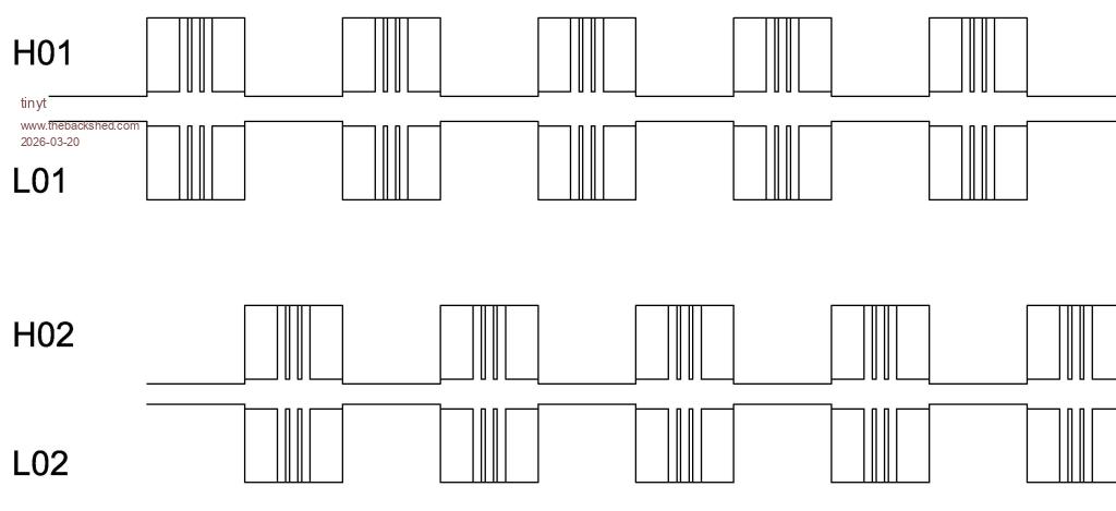
Ch1 L01 Ch2 L02
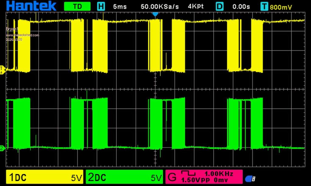
Ch1 L01 Ch2 H01
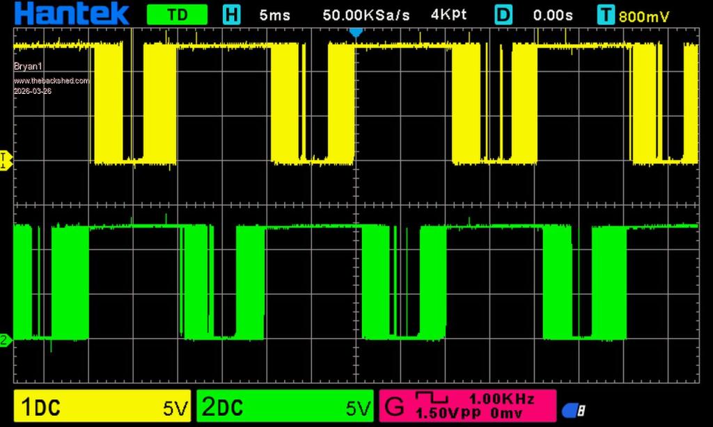
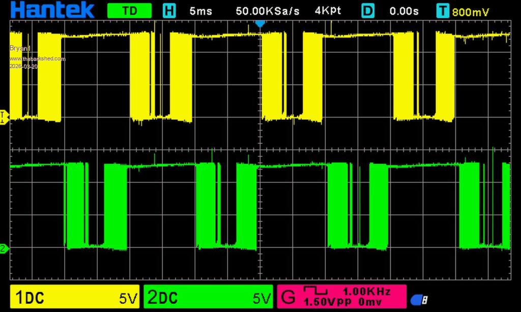
Ch1 1 L01 Ch2 H02
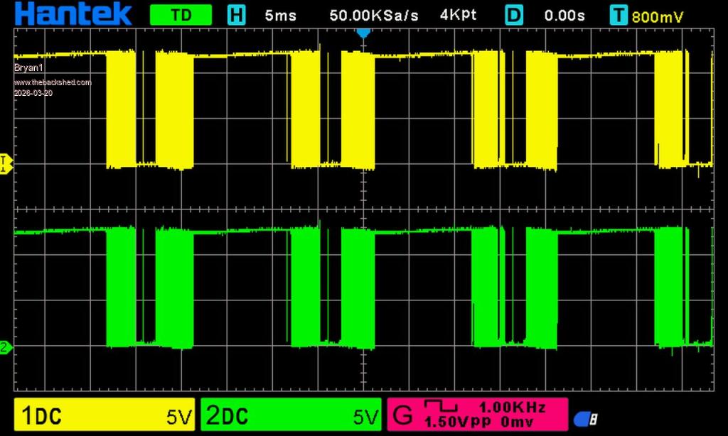
Ch1 L02 Ch2 H02
So after lunch time to put a NEW HY5608 mosfet on each leg for the next test.
Posted: 03:08am 20 Mar 2026 Copy link to clipboard
tinyt Guru
I hope you got your scope probe test points right.
Edited 2026-03-20 13:16 by tinyt
Posted: 04:01am 20 Mar 2026 Copy link to clipboard
Bryan1 Guru
Well put one mosfet on each leg and when I turned the control board on R52 the 20 ohm resistor started letting out that magic smoke so replaced both 20 ohm resistors on the high side only to find it did it again.
Posted: 04:48am 20 Mar 2026 Copy link to clipboard
Godoh Guru
Sorry to hear you are having so much trouble Bryan. i hope you can sort it out soon pete
Posted: 11:09am 20 Mar 2026 Copy link to clipboard
Revlac Guru
Hi Bryan, not sure whats happening there, I might make some time to put one of these boards together, I just ordered some parts (TIP41-42c thought I had some) most of the other stuff I have. Will be some time for it to get here, but have to build one anyway.
Posted: 02:15pm 20 Mar 2026 Copy link to clipboard
tinyt Guru
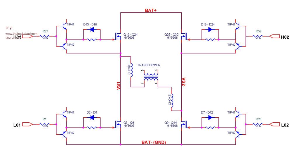
Here is a simplified schematic of the inverter.
In your scope capture of L02, H02 both waveforms are the same. So, Mosfets Q9 - Q14 and Q25 - Q30 conduct at the same time creating a short condition. Probably damaged the mosfets, the TIPs, and the IR2184s.
You have to make sure waveform time and voltage relationships for the signals are correct. Here is a sketch for reference, note the position of the wide lines with respect to their 0 volt.
Also, ideally, one should probe directly at the mosfet gates but a slip of the probe tip can cause damage, so it is safer to probe at the diode pins. If it shows good waveform, you know that the resistor and the TIP pair are working.
Edited 2026-03-21 00:54 by tinyt
Posted: 01:16pm 25 Mar 2026 Copy link to clipboard
Revlac Guru
Hi Bryan, Some parts have arrived and have been placed into the power board for testing, this power board says rev4 on the underside, is yours the same? With one fet per leg and tip's in place and powered, so far no shorts, more components and testing later.
Posted: 11:03pm 25 Mar 2026 Copy link to clipboard
Bryan1 Guru
Hi Aaron yes the board is a rev 4 and this morning I powered it up and yes there is a dead short.
Now ohming with one lead a L02 source pad and the other on L01 and L02 drain there is a a dead short so it does look more mosfets blown
So now the blown mosfet count is 24 and 10 of the TIP chip sets not to mention making a new control board and all those IR2184 chips.
So I am thinking this mad board can find a home in the shed and time for Mk.2 and build one of Mikes boards.
Posted: 11:50pm 25 Mar 2026 Copy link to clipboard
Revlac Guru
Just found something that might seem silly but not obvious. I have some 10 pin ribbon cable connector's from other grid tie inverters they look well made and good quality but the one I was about to try has the locating notch on the other side and in this case it reversed the positive negative polarity......not good, so to rule that out on other cables its worth checking positive side of the connector and confirm its the same on the controller and the power PCB. I will come back later tonight and try a few more things.
Yes the WG Inverter is a much more serious build and a lot of detail but very forgiving if testing and startup procedures are followed, I still recommend getting this one going if we can, the inverter build learning will be helpful with any future builds etc, I do see the pain you have had though.
Posted: 03:00am 26 Mar 2026 Copy link to clipboard
Bryan1 Guru
Well I took the mosfets off and set it up again to test
L01 L02
L01 H01
L01 H02
So from I can work out the top track on H02 which is on the top layer isn't making a connection, now I did solder in a jumper from the H02 pin to R52 the 20 ohm resistor.
When I tested with the mosfets in the R52 resistor would burn out, so I'm thinking of taking off the 10 pin connector and solder in some short equal wires to a new 10 pin connector so all the top tracks will have contact.
It is good to see the TIP chips are still proving good too
Edit: Now there is a short track on the bottom layer going to a via that I could scratch to expose the copper and solder in a jumper back to the pin on the 10 pin connector so H02 is connected. Edited 2026-03-26 14:08 by Bryan1
Posted: 04:39am 26 Mar 2026 Copy link to clipboard
Bryan1 Guru
Ok getting one step closer I put a scope probe on pin 7 of U2 and the wave form was lucky to be a volt so swapped out the IR2184 and now got a full waveform coming from pin 7 but no action at all on H02 with the scope.
Also I have confirmed the H02 pin on the 10 pin connector is in contact with R52 which was replaced this morning so I will replace the 2 caps and then try again.
Ok replaced both caps and put them in high to ensure the top solder joint was done and still no change.
So I remembered I had that 10 pin breakout cable so plugged that into the control board
Now the picture doesn't do justice to the scope but it is clear the H02 signal is going to the 10 pin connector.
I do have one pair to TIP chips so I will replace them and then thats everything replaced on the H02 side. Edited 2026-03-26 15:20 by Bryan1
Posted: 11:56am 26 Mar 2026 Copy link to clipboard
Revlac Guru
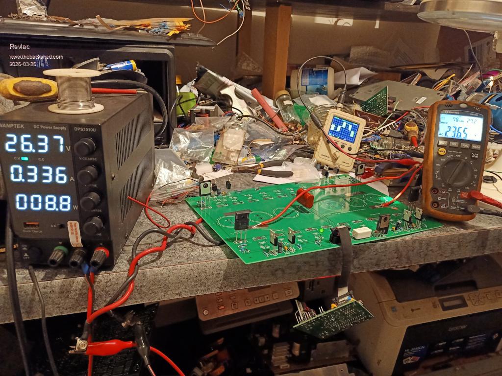
A little more progress, 10K resistors at the 4 TIP42C transistors, checked and everything still seems to work, next I connected a toroid with a 15v primary and a 10ohm 25w resister (all I had) between the VS1 and the one toroid primary no chokes in the primary yet but really should have spent the time to put one in.... then put a 4Uf cap on the secondary no filter and just a volt meter. Tested and got a little over 53vac at the secondary using 1 amp at 13vdc from the PSU, the 10ohm resistor was getting hot, it didn't like the 4uf cap on the secondary, reason would be I had no chokes on the toroid primary, so removed the 4uf cap on the secondary and tested all the way up to 26vdc input and now have 236vac on the output and using .33amp. Close to calling it working.
Next will be to make up the chokes and move the it outside to do a bit more testing, not liking it sitting on the bench for obvious reasons. Can't see any faults yet so yours should have been as straight forward as this has been.....up to this point....I can still mess this up so not going to call it 100% working until after.
Posted: 09:14am 28 Mar 2026 Copy link to clipboard
Revlac Guru
I still don't have the correct choke but tried a few that should of been some help, with 1 or 2 chokes on the primaries it was very easy to see well over 280vac on the secondary with the power supply wound up to 26vdc. now added the 4uF filter cap on the secondary and then turn the power supply anywhere past 14vdc and the sinewave looks great but it is using quite a lot more power than it should and the 10ohm 25w resister is stinking hot, other note is the Lab PSU is buzzing.....not happy, time to add a capacitor to the power board....now the PSU is happy. I did notice power consumption up to about 45w Idle at 230vac.... well thats far too high, so something is still not right, the board assembled for a 48v supply so haven't made any changes and just testing around 24-26vdc and a suitable toroid, didn't intend this as a build just wanted to see if compares to Bryans build.
Uses very little power without the 4uF filter cap on the secondary, I will have to dig in a bit more when I have some spare time.
Posted: 07:16am 29 Mar 2026 Copy link to clipboard
poida Guru
Revlac, maybe the high idle power is related to the very hot 10R 25W load.
typical idle power for my inverters is about 0.25 A at 50V DC so it's about 12W. This is with an output voltage of 235 VAC which is not enough to get the toroid into the beginnings of saturation, and a 2 or 3uF cap on the AC output. And a choke that is big enough. About 40 or so uH is enough for low power testing.
I like how you are testing things without the DC bulk caps in place. you can get away with murder like this.
Posted: 08:16am 29 Mar 2026 Copy link to clipboard
Revlac Guru
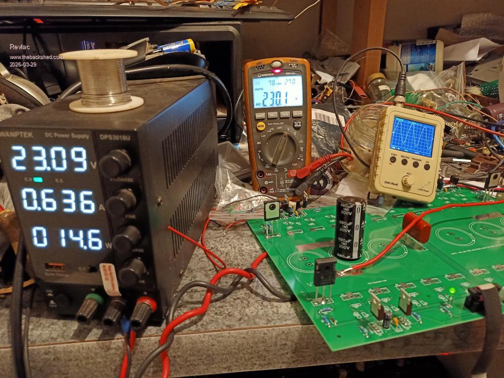
Thanks for the suggestion Peter , This is the first time I put a resister on the primary (of any build) and obviously not needed, I should have realised that earlier and removed it, I don't like blowing things up its so much extra work finding all the parts that are no good and replacing them, been there done that. I replaced the filter cap with a 4.7uF just removed from a grid tie inverter carcass wired it in place and.............beautiful result. No VFB connected yet, just the voltage from the Lab PSU. Photo says it all.
Now we just need Bryans built to work. Edited 2026-03-29 18:19 by Revlac
Posted: 02:02am 30 Mar 2026 Copy link to clipboard
Bryan1 Guru
Well had another go this morning Confirmed the H02 pulse was correct on U2 which it was, still nothing on H02 on the board with the scope. Now D25 was on 18 volts and R52 zero volts so scratched the pad for the H02 pin on the underside of the board of the 10 pin connector and soldered in a jumper.
So after that failed replaced the TIP chips so every component has now been replaced yet still nothing on H02. The other 3 legs are all showing correct wave forms too.
Just confirmed the H02 pin on the ribbon cable is connected via check with Ohms also checked continuity along H02 and everything seems to be right so just need to sort out why the H02 signal won't go thru.
Posted: 02:32am 30 Mar 2026 Copy link to clipboard
tinyt Guru
with no power applied on both the picoverter board and power board, try continuity check of the H02 at both sockets to trace where the disconnect is: Ribbon cable wire, Ribbon cable plugs. Sometimes IDC prongs of the ribbon cable connector do not make contact with the wire of the cable.
Edit: When I was making ribbon cables way back, I did not know that each ribbon wire 'bumps' should align with the mating 'notch' on the plastic IDC connector before pressing them together. This caused shorts and disconnects. Edited 2026-03-30 12:42 by tinyt
Page 23 of 28
The Back Shed's forum code is written, and hosted, in Australia.


 so replaced both 20 ohm resistors on the high side only to find it did it again.