| Menu | JAQForum Ver 26.09 |
| Menu | JAQForum Ver 26.09 |
Forum Index : Electronics : Wiseguy (WG) Inverter Build Discussions Australia
  Page 3 of 5 Page 3 of 5   |
||||||
Divide by 100. Inductance is proportional to N^2 |
||||||
Yes, the inductance is proportional to N^2 and divide by 100 if you want to get the inductance factor (Al). But for layman doing quick checks against other builds to verify core type it's fine to just check inductance per turn (divide by 10) or not divide at all IMHO. |
||||||
Thats sensible Analog8484, relative to where I and others are at with our capabilities and extent of project development. |
||||||
I think it best so show what the issue is with a real world example, so no one goes off on the wrong tangent. L = Nsquared x AL L = final inductance, N = number of turns, Al = inductance factor Assume N = 1 & Al = 1mH, therefore L = 1 x 1 x 1 or 1 Turn = 1mH Assume now N = 10, now L = 10 x 10 x 1 so L = 100mH for 10 turns Now divide the resulting 10 turn L = 100mH by 10 for 1 turn and we get 10mH ie Al now =10? But Al = 1mH and it is a constant so 10T and divide resultant by 10, then we are out by a factor of 10 in this example - it gets rapidly worse with the number of turns! Because we are dealing with the number of turns squared, the rise in L is not a straight line but exponential. The inductance factor Al is not directly proportional to the number of turns, but it is related to a single turn and the square root of the number of turns. Direct quotes below. Wikipedia: The inductance is proportional to the square of the number of turns in the coil Google AI: Therefore, doubling the number of turns in a coil doubles the inductance, and quadrupling the number of turns quadruples the inductance. Love AI - the world is slowly going to hell in a hand basket...... I actually don't remember AI ever giving me a correct answer and when challenged the reply is "sorry for your confusion, what you say is correct" - my confusion? go figure Edited 2026-05-18 11:33 by wiseguy |
||||||
Jake, great work as reported on the 'Inverter Building...' thread. Must be satisfying to see it working. How long did it take to put it all together? Can I get clarification again on a couple of points? Have I correctly understood that capacitor specification 1n5 is 1.5 nanoFarads/ 0.0015 µF, whereas 1u5 is 1.5 microFarads/1.5 µF? May we have voltage specs for capacitors as follows: - Power Board WG30 items C1-C6,9,11 1u capacitor - WG30 items C7,8 1n5 capacitor - LCD Board WG44 item C1 100n capacitor Are there any generally recommended sources for the nano chip, taking into account KeepISs' comments about looking for good vs bad chips and recommended cap & diode removals? Cap Board WG06 capacitors, again taking into account KeepISs' comments. What capacity and quantity is now recommended? 4,700 vs 10,000 uF, or something else? Does it matter? Control Board WG39 items J8 - J11 **(J10). The comment says ** DNL J10 (No Sync code yet). Can we get more detail about what, exactly, to order here for items J8,9 & 11, and for J10? |
||||||
Does the tolerance and/or the composition (thin film/ metal/ foil/ etc) specification matter for the resistors? I assume not, & if so, what are sensible specs? There's a dizzying array of options! Also for capacitors, especially smaller ones. Edited 2026-05-26 12:02 by GleamBright |
||||||
Yes you understood it. Up to my armpits dismantling the old LiFePO4 battery racks and rebuilding them in battery boxes, it's hard to get 115kg cabinets from the bench to the ground  , one down 3 to go. So a few quick answers. , one down 3 to go. So a few quick answers.IMHO 4700uf Caps are best, 4 mounted on each board (full board). This allows better cooling across 4 caps on each board. Using 10000uF limits you to a max of 3 on each board, and really, 3 per board is almost to much destructive power across the Fets. Around 19000uF on each board for a total of around 38000uF is nice. J10 is simply used as a sync output when testing with a DSO, makes nice synced locked stable waveforms. Caps C7,8 are 1n5 Film or Monolithic rated 63v or 100V The others are the same type and 63v, as 100V start getting a bit big, but I've fitted 100V in a pinch. LCD board are just 100nF 50v to 63v. Ill get some links to the boards, unless someone posts some before I get a chance. Hope I covered it all.  |
||||||
Resistors, metal film 1% as there is not much difference in cost, 1/2 watt unless specified as other. Capacitor types matter, follow specified types in BOM. Edit resistor type. . Edited 2026-05-26 13:09 by KeepIS |
||||||
I followed KeepIS advice and bought Keyestudio on Ali. |
||||||
Thanks, you saved me the time looking it up, I've bought quite a few of those, everyone has programmed and run perfectly, and very nice board and build quality. |
||||||
Thanks Jake, can't complain about the price and will take on board feedback from our in house IT expert. A couple more questions: Can you describe the monolithic capacitor type listed on the BOM in more detail, as I know this is not a surface mounted MLCC. There's no category for 'monolithic' on Digikey, where I'm compiling the first pass shopping cart. Re: resistor pitch specifications, 10mm for example. Is this equivalent to the hole spacing? as most of the catalogued axial resistors have lengths 6mm or less. I'm assuming 6mm will be ok as the leads will be bent to match the hole spacing? Where the capacitor footprint is listed as 2.54mm (0.2"), does this mean that the lead spacing should be 2.54 mm, but 0.2 inch - which is 5mm is also tolerable? |
||||||
Monolithic capacitor are Multi-layer ceramic capacitor, abbreviated as MLCC. I normally use them as bypass caps, like 100n (0.1uF), very small, bend leads to fit. MKT miniature polyester, normally 100V rated should be fine for the rest, except for, Electrolytic, Tantalum, and a few a Ceramic caps like C3, C14, C23, these should be easy to find. 1/2 watt metal film is the same size as normal 1/4 watt, yes leads are bent to fit the mounting holes, sometimes they are mounted vertically to save space, one way or the other, they will fit. Don;t sweat the resistors, a Resistor that dissipates more power than a standard 1/4 /1/2 watt resistor, is normally listed with the power level it requires. Other members might like to correct any of the above, I'm just generalising here. . |
||||||
R39-R42 on Control Board WG39.... no resistance value specified. What should it be? |
||||||
R39-R42 are not needed as you will be using U8 and U9, which are high current Drivers for the Power board Optos, and U6 should be a SN74AC86N. From memory there are no markings on the later controller PCB for those resistors.. Edited 2026-05-27 18:17 by KeepIS |
||||||
Things have moved along with our group and we are now in a position to issue a call for orders to intending builders of A) Wiseguy inverter V7C, single or dual stage B) 150V 45A MPPT controller, RogerDWs' PCB design, and C) an inductance tester. One of us wil be handling the PCB orders and another the key component orders, on behalf of paricipants, for domestic redistribution after receival from PCBway, Digikey & LCSC. There will be significant cost and time savings in doing so, in comparison to ordering individually. Intending builders are invited to PM me here with an email address & phone number for further info. Order cutoff date will be set in the third week of June. Edited 2026-06-06 20:35 by GleamBright |
||||||
Just to clarify the Inductance tester for forum members, am I right in assuming that the device in question is the design by Poida?, the second last post in the following thread. Induction Tester Great work on bringing this all together, I understand just how much effort and time this must be taking. |
||||||
We haven't decided yet, but are leaning towards solar Mikes' unit as recently posted, by virtue of the fact that Gerber files are available. Which one is recommended in your view? Can we get help in specifying the parts we need to order to build it? |
||||||
Both are very good designs, check for code availability for solar Mike, and there are a few surface mount components as this is what Mike uses a lot and had in his parts bin. You could PM Poida regarding the PCB, I'm sure it's available, parts for it would be simple as you could use one FET and one opto coupler from the WG power board parts, nothing special there. . Edited 2026-06-07 11:01 by KeepIS |
||||||
Now we are on the topic of making a Induction Tester it would be nice if we can set it up for dual chokes like this one I made back in the day. 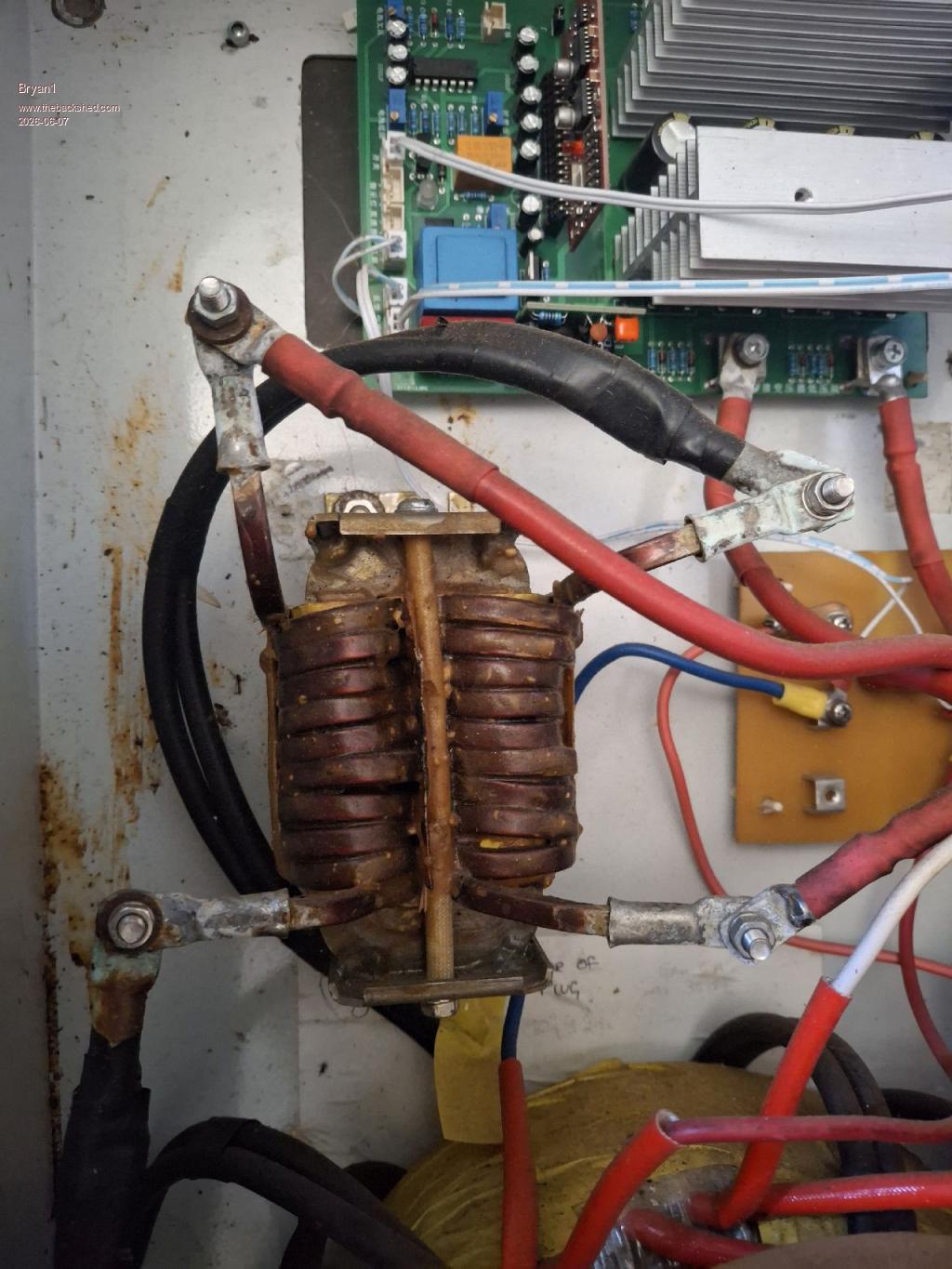 This design is Tony's where 10 turns on each side of the big dual choke on the Aerosharp. I did set it up with my first Ali inverter board and it ran fine powering 2 vacuums so that choke does work and it would be interesting to see at what current it saturates. Regards Bryan |
||||||
With the choke removed from circuit, join the transformer ends together then connect the inverter ends to the tester. |
||||||
| Page 3 of 5 |
||||||
 |
The Back Shed's forum code is written, and hosted, in Australia. |