So I finally got around to firing up some test code. First off, it works! Yay!!! But I have some questions.
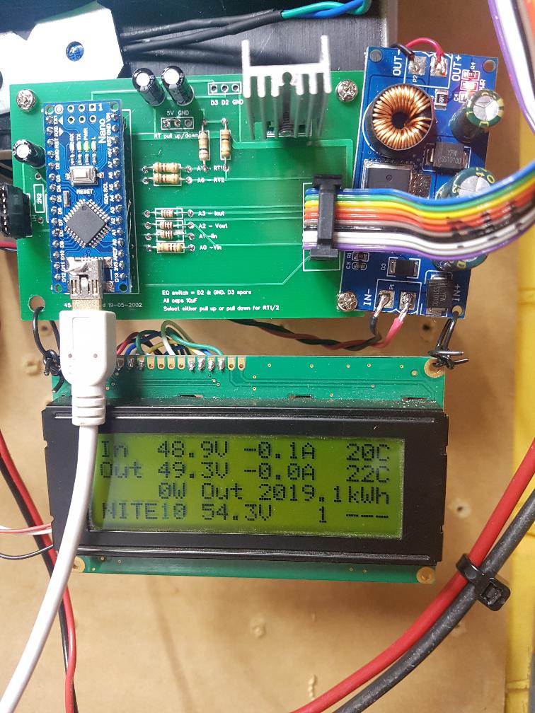
I'm using the code that was posted for testing, the DCDC converter code (buck_converter_nics_1_b4_nano_pwmserial_bb), but I modified it for use with my Nanocontroller with I2C LCD.
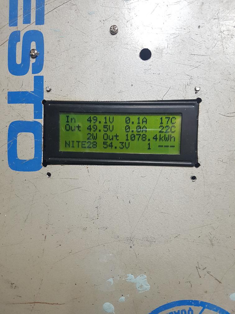
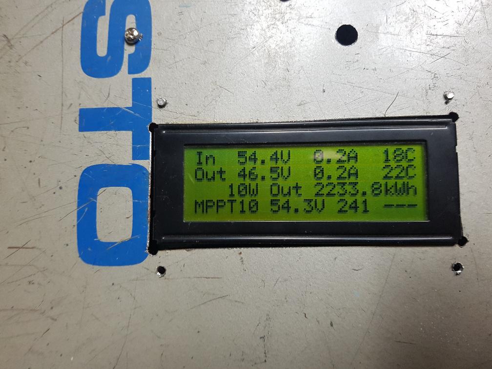
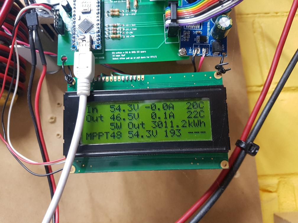
Upon running it, I found that both the input and output voltages read by the Nano do NOT correspond to the actual voltages. The input voltage seems to read a good ~10V higher than it actually is. Also, the current readings are negative.
I've checked my input (and output) voltage dividers, they're correct according to the Powerboard BOM & schematic I have (R5 & R7 are 47k, R6 and R8 are 2.7k).
But that means the scaling coefficients in the code are wrong (also, if the voltage dividers for Vin and Vout are the same, why are the scaling coefficients different?).
For xVin the code has 0.1564 and for xVout it has 0.102. The latter is NEARLY right, it results in the reading being about 1V too high.
Then I saw one post where you said it should be 1k and 47k to get a higher input voltage range, but the xVin coefficient doesn't work for that either.
So I "fixed" the coefficients and put in xVin=0.234 (using the 1k resistor) and xVout=0.09 (using the 2.7k resistor).
For the current sensors, the coefficients are also odd. The offset should be 0.6V, but is set in the code (oIin and oIout) to 127, which is a bit higher than 0.6, so the "zero" current reading is negative. I reduced it to 122. Then, the scaling seems a bit off as well: An ACS758 which I have used puts out 60mV/A over a 5V range, so the scaling should be 0.0816 instead of 0.792...I think.
These are better, but I think I can dial them in even closer.
Question: Were these values meant for different current sensors or a different setup?
I tested this up to 120W for the moment, since my benchtop power supply will only put out 5A.
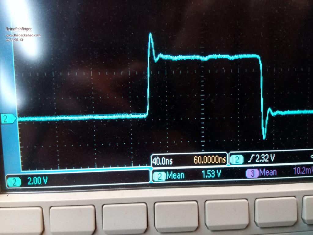
I checked out the PWM waveforms. Out of the Nano:
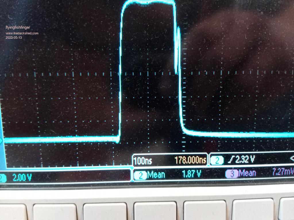
Output of the optocoupler before series resistor (note different time scale):
Gate of the MOSFETS (after series resistor). This one looks odd, but after reading the datasheet for the FDH055N15A, it's actually not that bad. The normal turn-on delay is 35ns and the turn-on time is supposed to be 67ns....which is about what we see here.
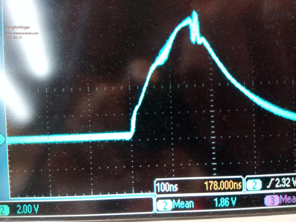
Question: 100ns on time seems very short for this MOSFET. But these screenshots might have been measured with NO load, so having basically 0% duty cycle makes sense for this case. Am I right there?
How do you characterize inductor saturation? Shunt / clip current probe? Will look at it again under load.
Thanks,
Rafael
Edited 2022-05-13 11:57 by flyingfishfinger

 .
.  .
.