| Menu | JAQForum Ver 19.10.27 |
| Menu | JAQForum Ver 19.10.27 |
Forum Index : Windmills : Old Dunlite Wind Generator
Nice to see someone else with an old dunlite. Mine haven’t progressed past sitting in the shed yet! |
||||||
Phil99 Yes, that is the commutator and it's in good condition/ hasn't been machined. The entire unit 'got away from' the seller when lowering the tower: it fell, damaged the blade tips and has been sitting idle since. The rest of the unit is largely intact, including the blade hub and counterweights. It needs a main bearing replacement. Old_Dunlite you have a big task ahead, based on the condition of your units, and I'm happy to collaborate. A commutator rewind is probably overkill if a step up transformer would do the same job albeit at a small loss of efficiency. Attached below is the wiring diagram from the operating manual. My understanding is that a PWM controller and diode would replace the power control unit and relay as described. In the original unit, the relay is a combined 'selenium dry rectifier' (older equivalent of a diode) and the power control unit is a mechanical PWM device. I'm just not sure what PWM or diode specs to order, nor how to wire/configure it correctly. 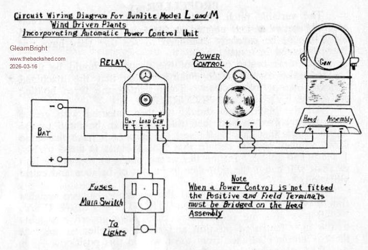 |
||||||
A transformer isn't going to work as your unit is d.c. (looking at old-dunlite's pics though makes me think that his unit is a 3phase alternator, which could be transformered to a different voltage). I don't know anything about these units, but is a 32v unit is designed to operate on a 32v battery or just output 32v? Or is it designed to charge a 24v up to 32v? Similarly for a 48v unit? Although i would tend to assume a '48v' generator is designed for 48v battery charging - i.e. up to 60v. But taking the 32v and 48v at face value, that means you need to get an output 1.5 x design: If the original blades were a low speed design, then a faster blade set might work. Running the field winding at 1.5 x 32v (i.e. 48v) would mean field amps are 1.5 x nominal too. Assuming this doesn't drive the iron into saturation, that would raise the output voltage to 48v. But, it would also raise the winding power to 2.25 x nominal. Without knowing the field resistance (and therefore nominal power at 32v) it's difficult to say if that would overheat the generator of not. Building a circuit to replace the original controller shouldn't be too difficult, particularly as your diagram suggests running without a controller is an option, but would need to know details such as field winding resistance, and max output amps. |
||||||
On old generators the stated voltage is the nominal battery voltage, not the charging voltage. So for a 32V unit the output would be 35 to 37V. In the diagram above the Note says if no Power Control (voltage regulator?) is fitted the field can be directly connected to the output. This opens up an opportunity as the DC to DC converter can do the regulating, so the generator output voltage no longer matters. Same as a solar charger where the panel voltage can vary a lot, except using a boost instead of buck converter. The Relay (reverse current cutout) would be replaced with a large diode. Either a Schottky or MOSFET Ideal Diode circuit for better efficiency. Edited 2026-03-16 12:54 by phil99 |
||||||
The manual states the following for the L and M models (this one is an M): Model L (1 kW) Model M (1.5 kW) Normal Voltage 32 50 32 50 110 Maximum Voltage 50 66 50 66 145 Maximum Amperage 20 15 30 23 11 and from earlier in this thread, resistances for the L model are: 32 volt machine: Field 27 ohms, Armature 0.4 ohms 48 volt machine: Field 50 ohms, Armature 0.6 ohms No resistance data available for the M model although it could be inferred? knowing that the only mechanical difference between the L and Models is the gearbox ratio (3.5:1 vs 5:1 respectively). Which answers the question: there is plenty of voltage to accommodate charging voltages substantially higher than nominal. re: running at higher speeds, the manual emphasises in upper case: 'MAKE CERTAIN THAT THE MAXIMUM CHARGE RATE IS NOT EXCEEDED', and the blade hub incorporates an (adjustable) variable pitch mechanism, with instructions to adjust the pitch governer to limit blade speed to achieve this end. I couldn't see a faster blade set as viable: they're a low speed design formed from sheet metal, and operating at higher speed would increase the risk of overspeed failure during high winds - this is mentioned in the manual. Edited 2026-03-16 17:04 by GleamBright |
||||||
Given the warning in capitals and that the governor is how the the current is normally controlled, another means will be needed if you override that. So instead you will need a voltage regulator that includes current sensing and regulation. Early Holdens eg. EH had a Bosch 12V 25A generator with a regulator box that had 3 step proportional relays for both voltage and current, as well as the reverse current cutout relay. You will need a solid-state equivalent of that. |
||||||
Ok, well if the existing mechanical variable pitch control is used, that should take care of max amps and mechamical overspeed, i guess. Your table of voltage /amps limits suggests the max volts for this unit is 50v, which, (as i think phil said originally) is a bit low for 48v battery charging. Just looking at field resistance: 27ohms at 32v is about 38w power dissipation in the field winding; 50v puts it up to 93w, so i would be reluctant to go past that. So i guess that brings us back to running it at its nominal voltage and using a boost converter: if the output is 20a max, then there are some fairly cheap ones on Ali that should work: 40a boost converter Although it can be run without a controller, i would advise using one, as it would reduce the risk of burn out, should there be a loss of load in windy conditions. I've used a simple opamp as comparator circuit for alternator regulators in the past: something similar should work here. But the issue may be voltage stability if the output is not connected directly to a battery, as the field winding is a big inductor, the field current can change quite slowly, meaning the output current cannot change suddenly if a load suddenly drops out. A very large capacitor on the output may suffice, or a small 32v battery. Edited 2026-03-16 19:08 by mab1 |
||||||
On my website: www.kdwindturbines.nl at the bottom of the menu KD-reports, there is a manual of a 27.6 V, 200 W battery charge controller which contains a voltage controller and a dump load. The dump load contains one heavy Darlington transistor and two 100 W resistors mounted to a large aluminium sheet which functions as heat sink. The dissipating power can be increased by conneting several dump loads in parallel using only one voltage controller. This system is meant for a 24 V lead acid battery. If you have a 48 V lead acid battery, you can connect two systems in series but the dump loads must be isolated from each other. Edited 2026-03-17 04:50 by Adriaan Kragten |
||||||
Some piccs of the haul & a quick inventory take: - 1 x functioning 50V L model, with tower - 1 x near functioning 36V L model, requiring refurbishment and new blades - 1 x spare 36V L model with components in various states of repair - 1 x near functioning 36V 750W model, requiring refurbushment - 1 x spare 36V 750W model, also with components in various states of repair. I want to see if I can upgrade the L models to 1500W. To do so, Old_Dunlite or anyone else, would you consider parting with your 5:1 gearbox drive pulley (&shaft) if you're not looking at completing your own project in the foreseeable future? 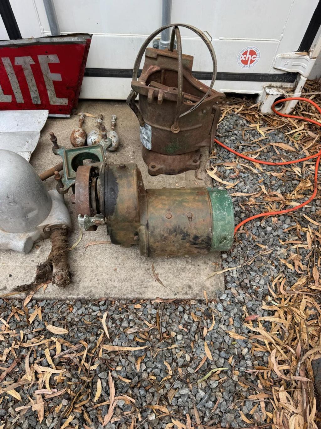 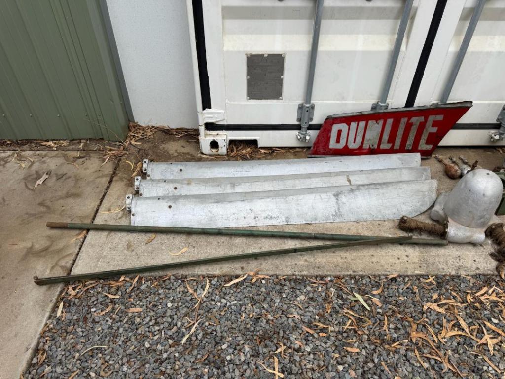 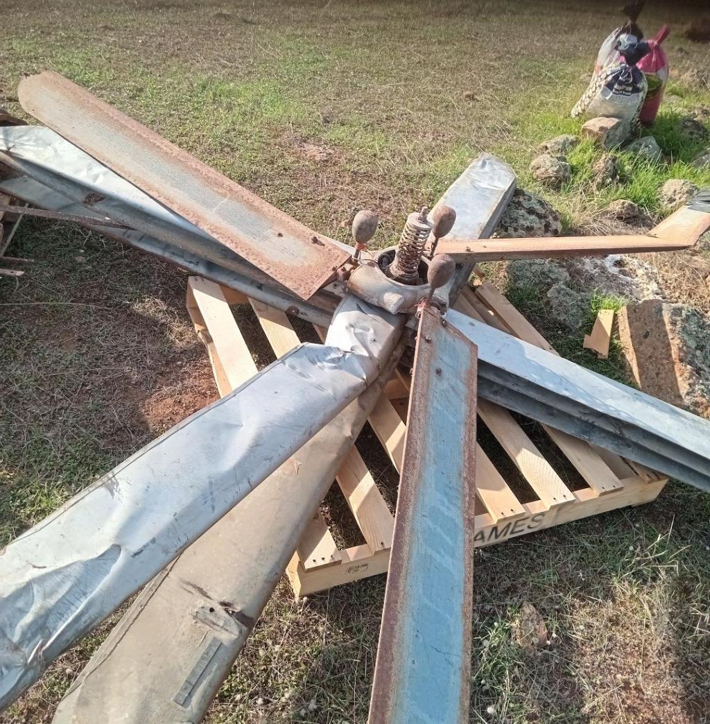 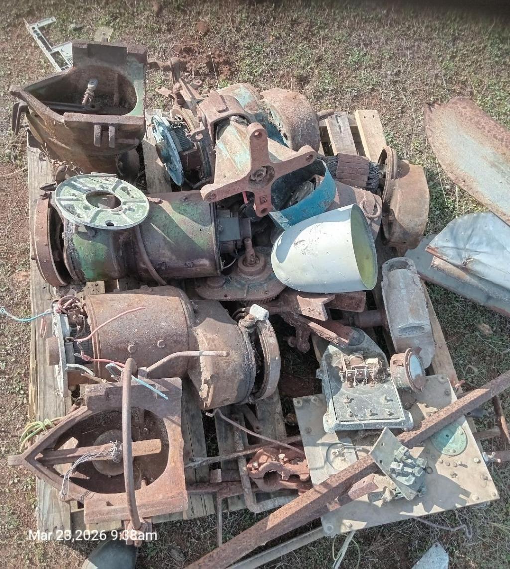 Edited 2026-03-23 17:09 by GleamBright |
||||||
When I was working in the wind Energy Group of the University of Eindhoven from 1975 up to 1990 we had a Dunlite wind tubine mounted at the top of the roof of our building. Dunlite was sold to Philips and Philips had asked us to test one. We found that the pitch control safety system was very unstable. This means that at a certain rotational speed, the moment caused by the centrifugal weights becomes larger than the counteracting moment of the central spring. The position of the centrifugal weights was such that once they start moving, the moment increases strongly. This results in a sudden very big increase of the blade angle. The tip speed ratio then becomes much lower and the rotor slows down. At a certain much lower rotational speed, the spring moment becomes larger than the moment of the centrifugal weights and then the blade turns back to the starting position in one big move. The system is certainly safe at high wind speeds but the functioning is far from that what you really want and that is that a little increase of the rotational speed results in a little increase of the blade angle. This is only possible if the centrifugal weights are positioned such that change of the position has only a very small influence on the moment and if there is almost no bearing friction. The real increase of the moment of the centrifugal weights is then only caused by increase of the rotational speed. More information about pitch control safety systems is given in my public reports KD 437, KD 622 and KD 654. Edited 2026-03-25 02:55 by Adriaan Kragten |
||||||
Adrian, is there any chance we could get copies of said reports and are there recommendations to improve the stability of the pitch control on the Dunlite systems? |
||||||
Further up this page Adrian supplies his website. https://kdwindturbines.nl I think the use of a simple coil spring to set the speed / current limit will always result in binary operation. Flipping to the feathered position when the speed limit is exceeded and flipping back at a significantly lower speed. The restoring force of a standard helical coil spring increases linearly with the compression distance, but the force exerted by the bobweights increases in a strongly nonlinear manner. For proportional control the spring needs to match that nonlinearity. Perhaps a "beehive" shaped coil wound with tapered wire and suitably heat treated. Another option would be a leaf-spring with several tapered leafs. Either would need to be manufactured by a specialist spring maker. Edited 2026-03-25 10:57 by phil99 |
||||||
All the reports I referred to are free public report which you can find on my website: www.kdwindturbines.nl at the menu KD-reports. To know about which subjects I have written reports, I advise to read the note: "Sequence of KD-reports for self-study" given at the top of the list with KD-reports. In the photo of the Dunlite you can see that there is an eccentricity in between the blade axis and the rotor axis. Assume that this eccentricity is called e. You can also see that a centrifugal weight is mounted at the end of an arm which is directly coupled to the blade. Assume that the distance in between the centre of gravity of the weight and the blade axis is called L. Assume that the angle in between the arm and the rotor axis is called gamma. The centrifugal moment which is produced bij the weight depends on the ratio e / L and on gamma. Chapter 14 of KD 437 is called: "Adding of a centrifugal weight to the blade". In this chapter, formula 43 gives the centrifugal moment Mc. This moment has been determined for four different ratio's of e / L and also for e = 0, so for the situation that the blade axis intersects with the rotor axis. The result of the calculations is given in table 6 and figure 8. Figure 8 is very illustrative. If e = 0, the maximum of the curve lays at gamma = 45°. If e = L, the maximum of the curve lays at gamma = 30°. The pitch control system is only stable if it works symmetrical around the maximum of the curve. For the Dunlite the arm L is rather short with respect to the eccentricity e. So lets assume that e = L and so we have to use the upper curve of figure 8. Assume that the total blade rotation of beta is 30°. So this means that we have to start with an angle gamma = 15° for the normal blade angle beta and that we have to end with an angle gamma = 45° for the maximum blade angle beta. In tabel 6 it can be seen that the values which is given in between brackets in the used formula varies from 2.4319 at gamma = 15° up to 2.5981 for gamma = 30 and up to 2.4142 for gamma = 45°. So the variation is only little. The counterbalancing moment which is supplied by the central spring also increases and how much depends on the spring stiffness. If the spring moment increases more at gamma = 15° than the centrifugal moment, the system will be stable. However, in the photo of the Dunlite it can be seen that the arm of the centrifugal weight is about in parallel to the rotor axis for the normal blade angle. This means that gamma = 0°. In figure 8 it can be seen that now we are at the start of the curve and so once the blade starts moving, the moment increases strongly. This is the cause of the instability. The stability of the system is also influenced by the bearing friction. A sensible functioning can only be obtained if the bearing friction is very small and this requires that ball bearings or roller bearings are used for the rotation of the blade around its axis. I don't know what bearings are used for the Dunlite. If sleeve bearings are used, there will be a lot of hysteresis in the blade movement. For the pitch control system as given in KD 437, the centrifugal weight is positioned behind the rotor (see fig. 7) and for the Dunlite it is positioned before the rotor. But the position of the axis of the blade with respect to the rotor axis is different and for both systems, the centrifugal force results in increase of the blade angle. Figure 8 out of KD 437 is therefore also valid for the Dunlite. Edited 2026-03-26 18:13 by Adriaan Kragten |
||||||
| The Back Shed's forum code is written, and hosted, in Australia. |
