Posted: 12:04am 29 Apr 2025 Copy link to clipboard
KeepIS Guru
No, I think the IDE version of AvrDude and more importantly the Configuration file has been modified to run with how Arduino IDE wants the bits set.
The information from the later versions is superior in every way. I believe the IDE settings for the configuration file could stopping you from setting some of the Lock Bits.
Notice the absence of other fuse access reads apart from what we requested it to do.
avrdude: Version 7.3 Copyright the AVRDUDE authors; see https://github.com/avrdudes/avrdude/blob/main/AUTHORS
System wide configuration file is D:\A_Varoius Backup Folders\__NANO\Avrdudess Loader\avrdude.conf
Using port : usb Using programmer : usbasp-clone Setting baud rate : 57600 avrdude: seen device from vendor >www.fischl.de< avrdude: seen product >USBasp< AVR Part : ATmega328P Programming modes : ISP, HVPP, debugWIRE, SPM
Programmer Type : usbasp Description : Any usbasp clone with correct VID/PID avrdude: auto set sck period (because given equals null) avrdude usbasp_spi_set_sck_period() error: cannot set sck period; please check for usbasp firmware update avrdude: AVR device initialized and ready to accept instructions Reading | ################################################## | 100% 0.01 s avrdude: device signature = 0x1e950f (probably m328p)
avrdude: processing -U lfuse:w:0xFF:m avrdude: reading input file 0xFF for lfuse with 1 byte in 1 section within [0, 0] avrdude: writing 1 byte lfuse ... Writing | ################################################## | 100% 0.00 s avrdude: 1 byte of lfuse written avrdude: verifying lfuse memory against 0xFF avrdude: reading on-chip lfuse data ... Reading | ################################################## | 100% 0.00 s avrdude: verifying ... avrdude: 1 byte of lfuse verified
avrdude: processing -U hfuse:w:0xD7:m avrdude: reading input file 0xD7 for hfuse with 1 byte in 1 section within [0, 0] avrdude: writing 1 byte hfuse ... Writing | ################################################## | 100% 0.00 s avrdude: 1 byte of hfuse written avrdude: verifying hfuse memory against 0xD7 avrdude: reading on-chip hfuse data ... Reading | ################################################## | 100% 0.00 s avrdude: verifying ... avrdude: 1 byte of hfuse verified
avrdude: processing -U efuse:w:0xFD:m avrdude: reading input file 0xFD for efuse with 1 byte in 1 section within [0, 0] avrdude: writing 1 byte efuse ... Writing | ################################################## | 100% 0.00 s avrdude: 1 byte of efuse written avrdude: verifying efuse memory against 0xFD avrdude: reading on-chip efuse data ... Reading | ################################################## | 100% 0.00 s avrdude: verifying ... avrdude: 1 byte of efuse verified
avrdude: Version 7.3 Copyright the AVRDUDE authors; see https://github.com/avrdudes/avrdude/blob/main/AUTHORS
System wide configuration file is D:\A_Varoius Backup Folders\__NANO\Avrdudess Loader\avrdude.conf
Using port : usb Using programmer : usbasp-clone Setting baud rate : 57600 avrdude: seen device from vendor >www.fischl.de< avrdude: seen product >USBasp< AVR Part : ATmega328P Programming modes : ISP, HVPP, debugWIRE, SPM
Programmer Type : usbasp Description : Any usbasp clone with correct VID/PID avrdude: auto set sck period (because given equals null) avrdude usbasp_spi_set_sck_period() error: cannot set sck period; please check for usbasp firmware update avrdude: AVR device initialized and ready to accept instructions Reading | ################################################## | 100% 0.00 s avrdude: device signature = 0x1e950f (probably m328p)
avrdude: processing -U lock:w:0xFF:m avrdude: reading input file 0xFF for lock with 1 byte in 1 section within [0, 0] avrdude: writing 1 byte lock ... Writing | ################################################## | 100% 0.00 s avrdude: 1 byte of lock written avrdude: verifying lock memory against 0xFF avrdude: reading on-chip lock data ... Reading | ################################################## | 100% 0.00 s avrdude: verifying ... avrdude: 1 byte of lock verified
avrdude done. Thank you.
Posted: 12:59am 29 Apr 2025 Copy link to clipboard
mab1 Senior Member
Hmm... i'm not so sure changing paths will work:
The paths (to avrdude and avrdude.conf) that work on the imac are via the arduino.app . when i try setting the path to avrdude.exe in your unzipped directory, it won't run the .exe files. that's what i was trying previously.
Unless i run them via 'mono'?
Sorry - off to bed again - will have a think for tomorrow.
Posted: 01:08am 29 Apr 2025 Copy link to clipboard
KeepIS Guru
Posted: 06:26am 29 Apr 2025 Copy link to clipboard
KeepIS Guru
Looks like the IDE config is setting Fuse Safe Mode. That means it will read the Fuses on entry, which your setup is doing, and reset any Fuse that change on Exit, once again seems to be doing that.
I've tested a few ideas and the best way to do this is to erase the Chip.
So don't wast time on trying anything else. Once you erase the chip, the Lock bits are cleared. These do not need to be programmed again.
Then upload the Hex File again and it should be fine. . Edited 2025-04-29 16:50 by KeepIS
Posted: 10:52pm 29 Apr 2025 Copy link to clipboard
mab1 Senior Member
Progress
1st: I traced the problem on the WG30 power board (fault no output from one of the 12v isolated power supplies). I'm a bit embarrassed about it though.
Doh! I must be getting old.
2nd: I found a version of zadig ( V2.2XP) which runs under xp (the version 2.7 included the win32 driver, but zadig2.7 won't run on win32 . Once I'd run that and set the right driver, avrdudess2.17 could see the usbasp
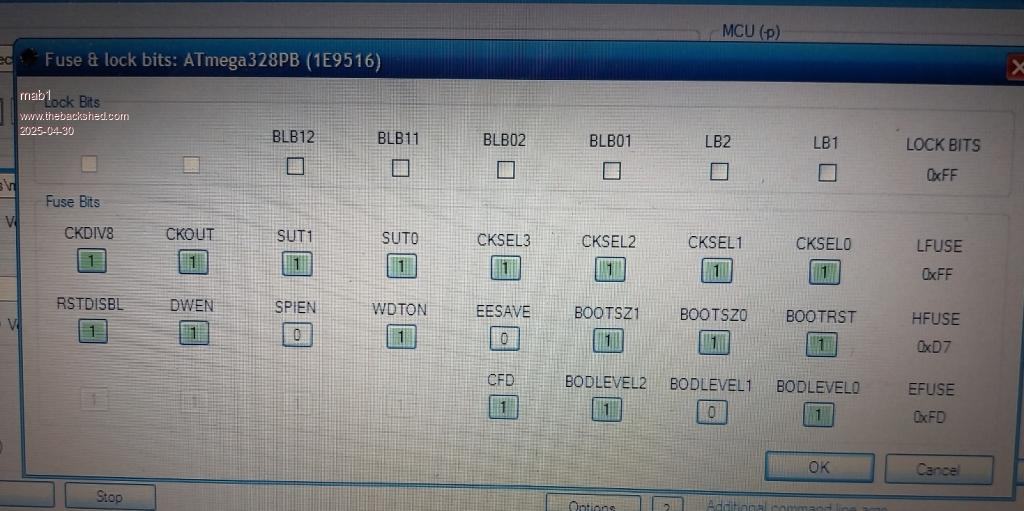
So I plugged in the 2nd nano we've been trying to set the fuses on in terminal on the imac. Read the fuses and clicked the bit selector:-
So it looks like your imac command lines worked after all and it was already right.
I plugged in the 1st nano with just the hex file, that I didn't try setting the fuses on - and it's bitselector map was correct too
Just as a sanity check, I plugged in a fresh nano - straight out of its wrapper. Checked the bit selector, and the lockbits were set 0xCF
Tried to set them using avrdudess and got the same error I was getting on the imac yesterday:
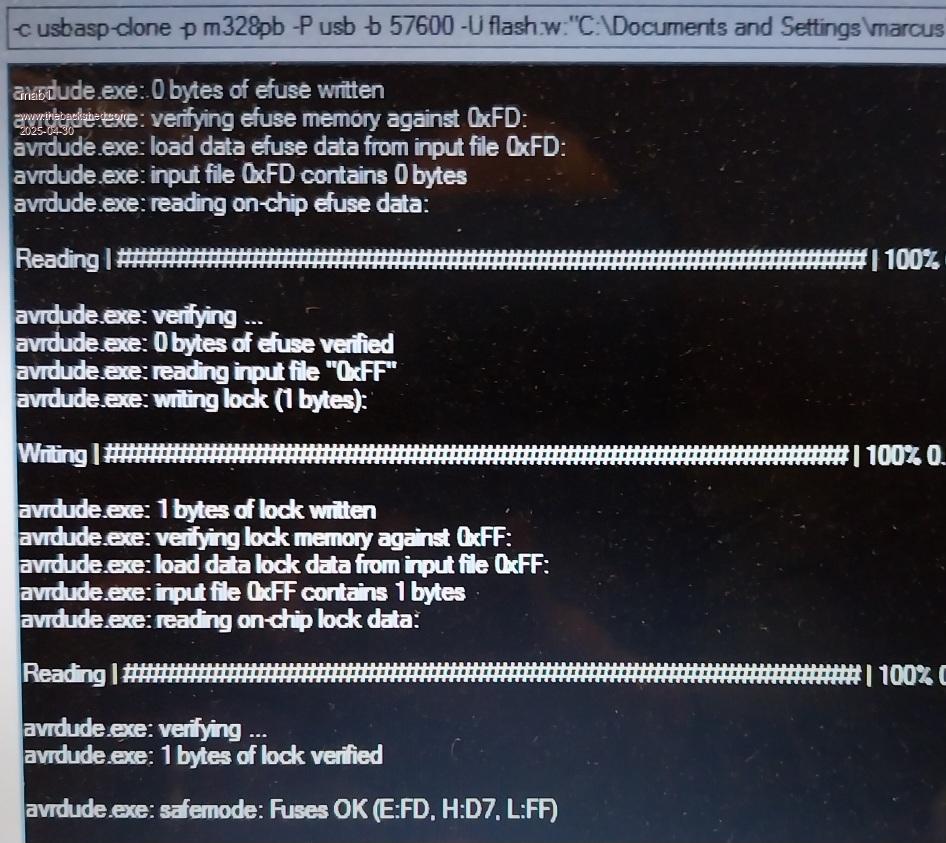
Tried it a couple of times but the error seemed to repeat. So set the tick boxes to set lock when programming and uploaded the hex file. That seemed to set the lockbits :
But I don't know how the lockbits got cleared on the original nano - unless uploading the hex file on the imac erased them anyway?
No matter though - it looks like I can (finally) use either avrdudess on winxp or command line on the imac
Posted: 11:10pm 29 Apr 2025 Copy link to clipboard
KeepIS Guru
Great to find such an easy fix on the Power Board, although I bet you were secretly happy to find that pin floating
Yes that is common problem with programming the Lock bits, when you upload the HEX with standard settings, the Flash is Erased first.
So, to erase the flash, the Lock bits are set to FF, after the upload, unless some other command is sneaked in, they remain off.
I found earlier versions AdrDudess do not return/display the Lock and general status bits correctly.
Normally you press each READ button twice (to be sure) and then press Bit Selector to display the results, but sometimes it's still incorrect
The Important Fuse Bit is EESAVE, it must be 0, this preserves your Settings when you upload a new Hex file.
Posted: 12:05am 30 Apr 2025 Copy link to clipboard
mab1 Senior Member
I'm going to have to get back to winding the transformer I guess
Posted: 12:45am 30 Apr 2025 Copy link to clipboard
KeepIS Guru
It's always a great feeling when all the effort and time we put in to assembling the Power boards and Controller produce what you hoped for
Yes, the dreaded Toriod - The hardest part of my Toroid winding is finding three Very early Solar Inverters for the Toriods, no winding except for 14 turns of 2G cable through 3 stacked Toroids, which takes all of 10 minutes to wind
At least now you have the incentive to wind one
Posted: 02:55pm 04 Jul 2025 Copy link to clipboard
mab1 Senior Member
Slow progress: it isn't just winding the transformer though - the process of taking the inverter off the workbench and building it into some sort of enclosure, thinking about ground planes (been reading about other folks noise/interference suppression work) all takes time. I've decided to build the inverter into the aerosharp box ( the transformer won't fit, but everything up to and including the chokes will: the chokes and kilovac relay are under the ally plate).
I've wound a primary on the aerosharp 3kva 250/230v transformer to get up and running. 400mA idle at 42v in with 230v out of the 250v winding.
Also, I'm transitioning from 24v to 48v with this inverter, so I need to build a 48v battery (done ) and start converting/ transitioning all the solar mppt (one poida mppt ready ) and diversion controllers over to the new system, all whilst keeping the existing system functioning until I've reassured myself that the new setup is robust.
The plan is to start with the new inverter / battery and one solar array, and start testing with various loads, then transitioning more and more sources / loads over to the 48v system.
Posted: 12:48am 05 Jul 2025 Copy link to clipboard
KeepIS Guru
Moving and working on a big inverter can be a real problem, imagine lifting 6 hefty Toroids in a complete inverter , a visitor asked me the other day "why is my inverter so big?" my response was, why would you want to make it smaller, it has a comparatively small footprint, it's just tall, and it can be disconnected, wheeled around and fixed in under 10 minutes should a power board or controller fail for any reason.
IMHO it would only be a component quality failure that would cause a fault in this inverter.
Your build idea looks good, keeping plenty of room to repair and/or modify is the best way to go IMHO, and good move going to a Nominal 48V system, I went through converting from an 24V system to 48V a few years ago, I went about the conversion exactly as you are planing to do with both systems running until it was tested under loads for a week or so . Edited 2025-07-05 10:53 by KeepIS
Posted: 04:14pm 06 Jul 2025 Copy link to clipboard
mab1 Senior Member
Thanks Mike
I do have a question regarding connecting big inverters to big batteries:
The battery I've built uses a JKbms with active balancing and 200A continuous rating and is about 13kWh nominal capacity, and I've got another 17kWh battery yet to be assembled (a UK supplier (Fogstar) of 315Ah grade B lifepo cells suddenly dropped their price from £69.99 to £39.99, and I couldn't resist ).
I know some people don't use a bms, but just a big DC fuse or circuit breaker, and an active balancer, and presumably relying on inverter/charger settings for min/max voltage.
If you are dealing with peak currents (up to 1200A in keepis' case iirc!! ) would you be happy with passing that through a 200A bms? Or would you put a big fuse/breaker between battery and inverter?
Posted: 11:15pm 06 Jul 2025 Copy link to clipboard
KeepIS Guru
The BMS will usually allow a short duration high current surge above the maximum current setting (see specs), however with high surge currents of around 800A DC, you really need parallel battery banks for a number of reasons.
As far as I'm concerned, my main reason for using a BMS is for monitoring each cell voltage and to disconnect if "ANY Cell" is over or under voltage and to monitor/control charge current. The BMS I use are 200A and 250A rated and I have 4 banks of LiFePO4, 800A is where I set my Inverter to trip, but 1000A is still no problem for the 4 bank BMS.
I don't trust FET switching in a BMS, so I also include a big 80A fuse on each bank, typically these fuses easily hold over 300A each for a few seconds or more. This also helps protects the Solar charge input, wiring and parallel banks from each other and is my last line of defense if all else goes pear shaped
I also use separate 5A balancer on each BMS/Bank, as usual these also monitor each cell voltage (more wiring), I'm planing on building a bigger balancer and using that alone to protect each battery with a high current power saving sealed high current high voltage solenoid. Reason - I worry about supply chain problem in the future and want something I can use when a BMS eventually fails. That would mean I can build or repair the entire DC -> AC conversion electronics.
No mater what others use, they must absolutely monitor each and every cell in a battery bank. _ Edited 2025-07-07 09:25 by KeepIS
Posted: 11:40pm 06 Jul 2025 Copy link to clipboard
mab1 Senior Member
Cheers; I guess my spur of the moment decision to buy a 2nd battery gives me extra peak current headroom as well as extra capacity .
I prefer to have a bms for the same reasons, but I guess I was worrying about if the bms interprets the surge as a short circuit and disconnects.
I don't expect to see start currents like yours, so two 200A bms's then should suffice, with additional tomzin dc breakers or fuses (have some forklift fuses, 80a and 200a, but suspect they're designed for lead acid short circuit current not lithium).
Posted: 01:16am 07 Jul 2025 Copy link to clipboard
KeepIS Guru
The second battery was definitely good idea
Those fuses will be the same for either battery type, large 80A fuses (usually slow blow) seem like a low value but are needed and work well in this situation, just check the voltage rating for the fuse and holder is around 48Vdc and not 12V.
Most people don't realize that just three small (SMPS) power blocks, two for the dual LCD screens and one for my very small NUC computer will pull over 300A peak DC input for 8 out 10 times on power up with a lightly loaded Inverter AC output < 800W.
It may be a short transient but the FETs still have to switch that current and more.
From memory Poida found his single Mac-book supply did that. _ Edited 2025-07-07 11:18 by KeepIS
Posted: 11:07pm 14 Jul 2025 Copy link to clipboard
mab1 Senior Member
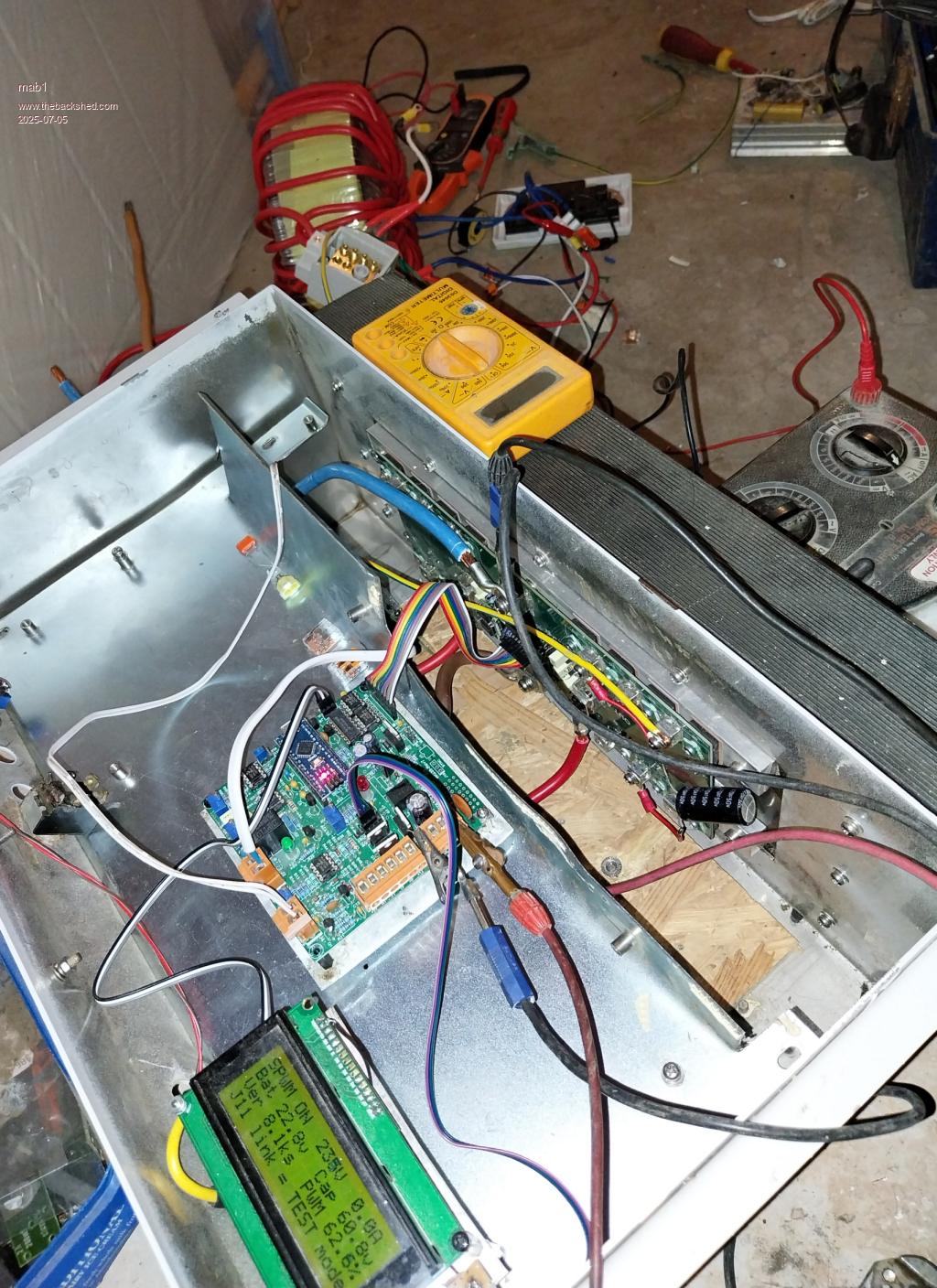
Having attached the cap boards with caps to the power board, i did have an issue:-
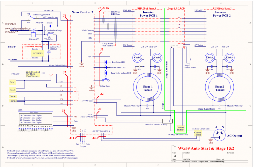
when i turned the inverter off, the brain board (WG39) seemed to be getting enough power from the capacitor bank to cause the nano and display to power up momentarily and keep cycling on and off until it fades to a flickering of the leds (i have installed Wiseguys 5v reg with monitor function, so must be that which cycles on and off? or the kilovac economiser cct?).
I'd followed Wiseguys schematic i found somewhere(copied below) for the on/off swt and cap precharge (10ohms), and when turned off the power appears to pass via the precharge resistor, then kilovac solenoid, to the Solenoid Q5 protection diode, D14, to +48v on WG39.
I have solved the issue by putting the +ve supply to the kilovac solenoid on the other side of the diode (i.e. +48v pin 2 of J1, but that does mean it is pulling power from the +48v cap on WG39 when you switch off . Is this OK?
Is there a better way of connecting the on/off swt, precharge resistor and kilovac that i've missed?
In answer to the question of the voltage rating of my forklift fuses: i believe they're 72v , although they don't have it printed on them. Edited 2025-07-15 09:09 by mab1
Posted: 12:20am 15 Jul 2025 Copy link to clipboard
KeepIS Guru
The Nano should not appear to restart with a standard 5v regulator.
Check the "Low voltage cutoff" and "Restart voltage" settings in the Menu, IMHO 10Ω may be to low a value.
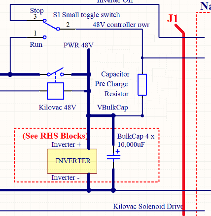
FYI This is how mine is wired:
Note: I use a 30Ω resistor and the Kilovac positive "MUST" connect to the the Cap Bank, IE. After the precharge resistor.
_ Edited 2025-07-15 10:38 by KeepIS
Posted: 01:05am 15 Jul 2025 Copy link to clipboard
mab1 Senior Member
Thanks, your schematic doesn't have the diode, so presumably when you switch off the nano and display remain active until the cap bank has discharged.
To be clear, when mine was cycling on and off, the inverter wasn't coming on, just the display showing 'off', then going blank and re-initialising.
I'll follow your schematic then ; I didn't really like having the solenoid pulling the input of the 12v reg down, as I've killed voltage regs in the past by pulling the input down faster than the output can fall.
Coincidentally, I broke one of the legs off the 10ohm whilst fiddling, so it's now 47ohm Edited 2025-07-15 11:05 by mab1
Posted: 01:57am 15 Jul 2025 Copy link to clipboard
phil99 Guru
The standard protection for that condition is a reverse diode from input to output.
Posted: 03:30am 15 Jul 2025 Copy link to clipboard
wiseguy Guru
The sequence at turn off is toggle switch turned to off, inverter ramps down, solenoid opens - there is no path to ground that I can see via the solenoid after ramp down and solenoid drive to ground (via FET which just turned off) opens.
I agree with the sneak path diagnosis via the solenoid catch diode - gotcha!
The KeepIS modification is probably the simplest cure, I'm not sure why I had not experienced the display toggling off and on at shutdown, but maybe my 24V solenoid and DIY economiser add on somehow negated the effect, or maybe I miswired it
Good to see your inverter coming along.
Page 6 of 8
The Back Shed's forum code is written, and hosted, in Australia.


 I must be getting old.
 . Once I'd run that and set the right driver, avrdudess2.17 could see the usbasp
 and it was already right.
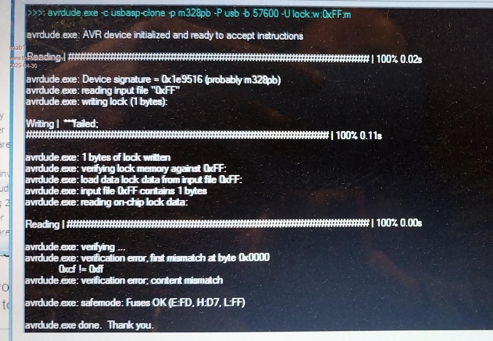


 , a visitor asked me the other day "why is my inverter so big?" my response was, why would you want to make it smaller, it has a comparatively small footprint, it's just tall, and it can be disconnected, wheeled around and fixed in under 10 minutes should a power board or controller fail for any reason.
 ) would you be happy with passing that through a 200A bms? Or would you put a big fuse/breaker between battery and inverter?