| Menu | JAQForum Ver 19.10.27 |
| Menu | JAQForum Ver 19.10.27 |
Forum Index : Microcontroller and PC projects : PicoMiteHDMIUSB motherboard reference design
OK, I used a CANO KIT PI 3 PSU and now no devices cause a boot loop. Thank you for that. My 3rd party PS4 wireless works perfectly. All three of my OEM PS3 wireless are recognized but do not work with matherp's test program, but that OK, My 2 3rd party wired PS3 controllers are recognized but don't work (they really are oddball controllers) so at least I have the PS4 which is the nicest of all of them and the generic SNES. As long as I have some options it's all cool. I will have to forgo the PS4 controller when I need to connect to my PC. I am just figuring out all the limitations and options of what I have on hand that I can use with this board. FYI The super inexpensive PS4 controller that works is by VOYEE I got from Amazon. |
||||||
I can offer this version of the universal PicoMite board with two video outputs, HDMI and VGA. If you make both versions of video outputs on the board, you will get a universal board for both HDMI and VGA video output. Both video outputs are connected to the same Pico2 ports with their own resistors. This solution has already been tested in other projects and VGA does not interfere with the operation of HDMI (even if it is connected). Moreover, there is a method for automatically determining the type of connected monitor at startup by the state of the ports (with VGA connected, they are all in logical "0"). It is also possible to implement two VGA video output circuits, VGA222 (64 colors) and VGA121 (16 colors). Or you can come up with some kind of palette switching with the remaining two ports. 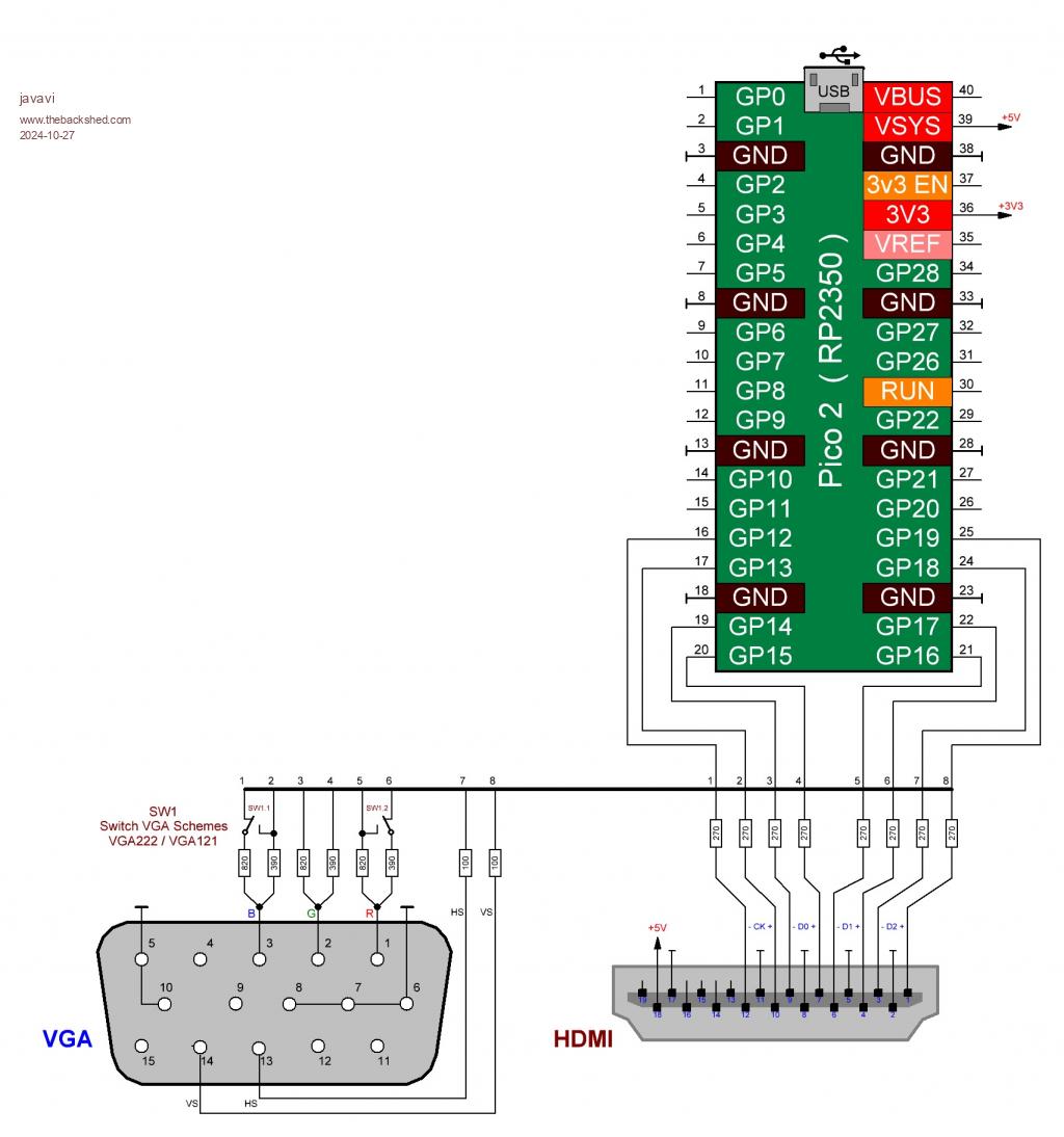 |
||||||
Just got some of the latest boards made by JLC 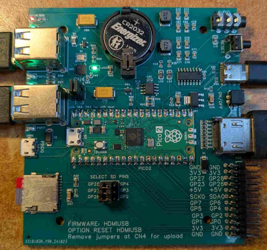 All the design files are now available on github This includes a dxf file for matching end-plates for the MULTICOMP MCRM2015S or HAMMOND RM2015S box. I will have 4 of these boards available for sale in the UK in about three weeks time. Cost to me including shipping and import duty was GBP24 each so add UK postage and that is the cost. You will need to supply and solder a Pico2 to complete. As before the board includes a 4-port USB hub for connecting keyboard, mouse and gamepads, HDMI output, battery backed real-time clock, CH340 console (if required), SDcard, and PWM audio. Everything you need for a boot-to-Basic computer. |
||||||
Hello Plasma, is there already a new status here? I haven't received any further news from you yet, or have I missed something? Matthias |
||||||
Hi Peter, Please can I reserve one. Let me know a total inc. postage and how you would like to be payed. Regards Kevin. |
||||||
Hi Peter I would like one also please. As Bleep said ' Let me know a total inc. postage and how you would like to be paid.' Thanks Dave |
||||||
Bleep and tritonium have one each - one left. I'm away for three weeks so it will be when I get back. I'll PM you then for your address. You can pay when I've shipped and know the shipping cost |
||||||
Sorry wrong thread. Edited 2024-11-02 09:50 by phil99 |
||||||
I hope you got my PM asking for one. John |
||||||
No, but I'll put you down for the last one |
||||||
Now that we have WII port commands, How would one wire up a WII nunchuck port to this board? are the GPIO pins on the back sufficient to do it? I have an extension cable I can harvest the port from so I would like to make a cable that I can just plug into the GPIO pins. Thanks. |
||||||
Yes connect to pins SCK0, SDA0, GND and 3.3V. |
||||||
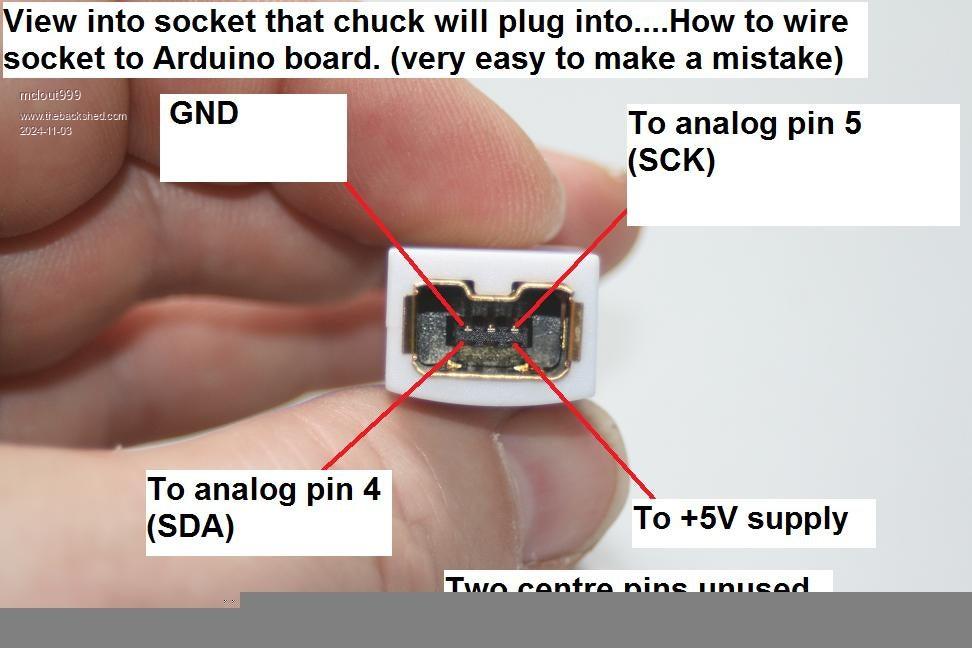 Do I connect them directly to the corresponding pins on the connector and do I need any resistors? the page I found was for an Arduino Board and it suggested 5V and a couple of resistors. here is the link to that article. https://www.instructables.com/Wii-Nunchuck-as-general-purpose-controller-via-Ard/ I am sure it is different for this board but I want to make sure. Thanks. |
||||||
The WII controllers are 3V3, not 5V. Apart from that the above is correct. You connect it directly. Another link here |
||||||
Thanks. I plan to cut down a 4O pin IDE cable and wire in a pigtail end of my extension cable. Now I bet that magnificent beloved maniac matherp will cut a new design for the PICOHDMIUSB with the WII port included. Either way, the cable looks like a very easy project. Are there any concerns if I make my cable and I offset the IDE end by a pin or 2 and fry something? I hope that will not be a problem. Witch end of the GPIO pins should I take the ground and 3.3V so that would be less likely" I think maybe I should include a row plugged wholes to ensure it can't be plugged in wrong and a label indicating the top. |
||||||
I tried to do a WII connector on the PCB edge like the CMM2 but it doesn't work in the little Hammond enclosure. In the CMM2 box there is room to lift the PCB up to allow the WII plug to go underneath it but you can't get away with that due to the limited height - if you want much else on top of the PCB anyway. I did it on a little "open" board some time ago and it worked reasonably well. I'm not a great fan of edge connectors without gold plating though. You can still get PCB sockets for the WII plugs on AE. I think there are only one or two suppliers though. Personally I'd use a 2x6 connector on the pins towards the centre and label the top. If you set the SD to use the higher number pins that leaves a good selection of useful pins. |
||||||
Hi Mick, Just ordered some nunchuck PCB connectors (they are 73 ct each). I (8 month ago) bought a WII classic controller. Not giving that up yet for the sake of USB. Especially now I know it works great with PETSCII. Volhout Edited 2024-11-04 02:01 by Volhout |
||||||
Hmmm... Gives me an idea.... :) |
||||||
Does anyone have an easy way to test my new WII port adapter? Thanks. I used an old FDD cable as I have so many. Here it is. 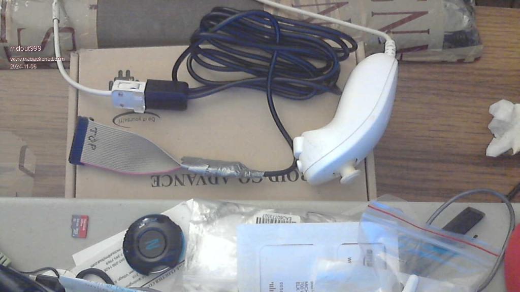 I chose to leave most of the extension cable length and I hope that was not a mistake. If it works I think my next project will be to wire a double pole double throw tagal switch on the jumpers for programming so I don't have to take the case apart to flash it. Regarding the boot button on the PICO 2 I have been thinking of making a tube that sits around the boot switch that comes out of the top of the case (wooden skewer as a actuator), I think I'm going to wear out the screw holes so I have just been taping it shut for now Edited 2024-11-06 03:34 by mclout999 |
||||||
Hi. I have been testing my new WII NUNCHUCK cable I put together a little program to test program (not great but it will show if the nunchuck is being read) Wii Nunchuck OPEN START: Print DEVICE(NUNCHUCK C); Print DEVICE(NUNCHUCK Z); Print DEVICE(NUNCHUCK JX); Print DEVICE(NUNCHUCK JY) Pause 5 GoTo START I run this and it works for a few moments and then locks the system up and sometimes it throws a prompt that says "Enter Pin or 0 to restart" I just tried again and it seems to work after I turn it off and unplug the USB C cable for a moment then I get that prompt when I Ctrl C to break it. Not sure what I happening here. Any Ideas? Thanks . |
||||||
| The Back Shed's forum code is written, and hosted, in Australia. |

