
| Menu | JAQForum Ver 26.09 |
| Menu | JAQForum Ver 26.09 |
Forum Index : Microcontroller and PC projects : Pico Computer 3 - One board to rule them all
  Page 6 of 9 Page 6 of 9   |
||||||
The German group order people had gotten some indication that the parts would become available sometime in August. Might be worthwhile to check again later. ~ Edited 2026-08-03 21:53 by lizby |
||||||
Thanks. (I can't find them, either.) Let me know if things change and you're able to order some built ones, please. John |
||||||
I've found a fault on the current PC3 design files (all boards so far made). This causes the ch334 hub chip to get hot, particularly if the programming cable and usb-c are both left plugged in and even when the switch is set to hub. Some time ago I swapped versions of the CH334 chip to use the CH334U as the previous variant had a bad batch at JLC. What I hadn't understood is that this variant has an internal 3.3V regulator. It has two pins 20 and 21 marked 3.3V and 5V on the datasheet so that is how I connected them. What this means is that if the regulator in the CH334U is producing a higher voltage than the LM117 then the hub chip is trying to power the whole board and hence getting hot. The correct wiring is either 3.3V on both the 3.3 and 5V pins, or 3.3V pin bypassed to gnd with 0.1 and 10uF caps. In addition R92 currently pulls up to 5V (only 10K so not serious) whereas it should pull up to 3.3V although there is an internal pullup so it is not really needed at all. If the board isn't giving any issues then you can leave it as-is. If the ch334U is getting hot then you can mod the board as follows: Cut the 5V trace to pin 20 between C67 and the pin. Short pins 20 and 21. Remove R92. I will post revised gerbers shortly. 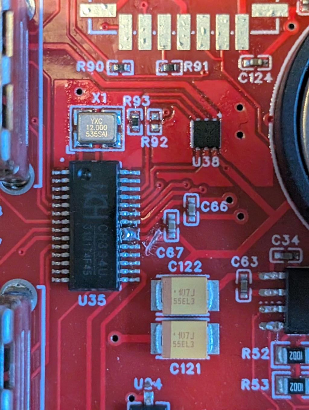 |
||||||
Updated design files now on https://github.com/UKTailwind/Pico-Computer-3/releases Edited 2026-08-04 02:11 by matherp |
||||||
The steps I use turn off the switch for the hub insert the programming USB cable holding down the reset button then program the board, once the prompt on the computer goes away take out the programming USB cable insert the C-USB then power it up. So at NO time are both USB cables are on the board. By the way Peter I'm running V0.12 of the micro-python is this the latest version? |
||||||
|
||||||
Thanks for that Peter  Mid way thru yesterday I upgraded board 2 to V.14 and it ran the club.py straight off the boot with no problems. So did Board 1 and by the end of day had both boards transferring csv files and grainy jpg files between each other over wifi. Mid way thru yesterday I upgraded board 2 to V.14 and it ran the club.py straight off the boot with no problems. So did Board 1 and by the end of day had both boards transferring csv files and grainy jpg files between each other over wifi.Regards Bryan |
||||||
Received my Pico3 from Grogster, and was doing a bit of setting up. I have set OPTION I2C GP20,GP21. I can set the current date and time using RTC SETTIME, the 3v. battery is fitted. When power is removed and reinstated the time has not been kept, and I have to use RTC SETTIME again. |
||||||
Perhaps check that 3V from the cell is making it to the RTC chip. On the underside of the board the cell holder terminals are accessible or on the top side C63 is across the RTC backup supply. Edited 2026-08-07 15:07 by phil99 |
||||||
Thanks Phil, I've already done that, checked OK. |
||||||
Hi Palcal - I received my PC3 board from Grogster recently and went through the same process. Have you included OPTION RTC AUTO ENABLE |
||||||
Hi Rodger, no I didn't set that option, I'll have a look. |
||||||
Thanks Rodger, That did the trick. I also forgot I had to use RTC GETTIME to reinstate the time. Edited 2026-08-08 07:18 by palcal |
||||||
Alternate gerbers posted at https://github.com/UKTailwind/Pico-Computer-3 . Either 3.1 or 3.2 is fine. 3.2 replaces an out-of-stock part in 3.1 with an equivalent Edited 2026-08-10 01:18 by matherp |
||||||
Hi Peter, I'm looking at and comparing the schematics of the Pico Computer 3 and the PicoMite HDMIUSB motherboard V3.0. I'm not entirely clear on the allocation of the RP2350B ports below the GP23 for connecting devices (SD card, Wi-Fi module, RTC timer signals). If possible, could you explain the reasoning behind choosing these ports over the PicoMite HDMIUSB motherboard V3.0 ? Why was the order of the SD card lines changed, why were these ports chosen for the RTC timer signals, and how does the SPI bus work for the Wi-Fi radio module? 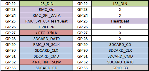 Edited 2026-08-10 04:40 by javavi |
||||||
Hello Everybody! If somebody has 1 pc (or 2 pcs also good) Picocomputer 3 for sale or planning to order it and want to share costs please write me a message. I’d like to test Mpython on it, and of course fantastic Picomite. Thanks! G@bor |
||||||
I can confirm that matherp's fix for the hot USB chip problem worked on my one PM3 board that had that issue. Future orders will make use of the updated gerber set. 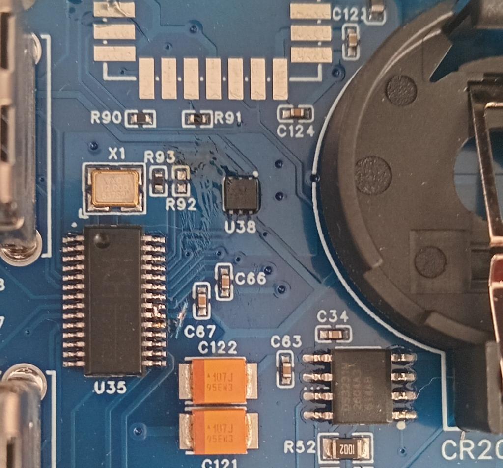 I have five assembled, programmed PM3 boards here, if anyone from Kiwi Land(New Zealand) wants one. If interested, send me a PM. |
||||||
I'd like to buy an SD card and have a quick question to be sure: What is the maximum supported size of an SD card for MMbasic, MicroPython, and Fuzix (on the Pico Computer 3)? Regards Edited 2026-08-14 23:49 by dddns |
||||||
@ dddns from the manual |
||||||
I now have the WiFi and PSRAM soldered in. Everything seems to work as it shoul except for the mouse. Moving the mouse left and right causes the cursor to move up and down, left clicking does nothing, right clicking moves the cursor one position to the right and clicking the scroll wheel acts like TAB and moves the cursor a few positions to the right. The mouse cursor is a white square and the normal cursor is still there and does not move at all unless I press the arrow keys. Also when I boot it tells me that the mouse is connected on chanel 2 and the keyboard is connected to chanel 1 and also the keyboard is connected to chanel 4. Edited 2026-08-15 12:47 by palcal |
||||||
| Page 6 of 9 |
||||||
 |
The Back Shed's forum code is written, and hosted, in Australia. |


