Posted: 07:16am 11 May 2025 Copy link to clipboard
FET cemetery Regular Member
Ordered some physically smaller resistors, will assemble my second power board with them.
The 5 scope traces I posted yesterday are pretty much what I would expect with everything working properly, it's only the addition of the big toroid that makes things go sideways. Switching noise going where it shouldn't has to be a possibility.
Posted: 08:38am 11 May 2025 Copy link to clipboard
KeepIS Guru
I think wiseguy is correct and the resistors may not make a difference, but from the point of view not having the resistors hovering over the main output planes, it's still a good idea to fit physical small units.
There is obviously something not right, you may have to check all values on the power boards, especially C7, C8 and R18 to R20. Sometimes the AC waveform can look reasonable when lightly loaded, but turns to S#$T driving the extremely low impedance of a big heavy gauge toroid primary.
Until you can get Idle current at 18V into the ball park below 360mA then you have a problem.
The 97% PWM at the higher voltage would indicate a major problem with the inverter trying to get to 230Vac, it's having trouble by the sound and the current at that level.
I'm sure wiseguy will have more insight once you get the adjustable supply, that will help us get a much better picture of what's happening. . Edited 2025-05-11 18:42 by KeepIS
Posted: 09:51am 11 May 2025 Copy link to clipboard
FET cemetery Regular Member
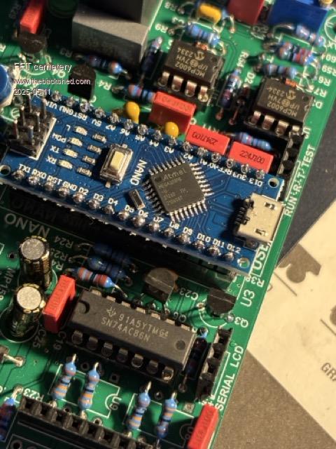
The components you mentioned are all correct, just wondering if I've got this right? 74AC86 into 33R resistors on the nano board then driving the 120R's on the power board.
Posted: 03:57pm 11 May 2025 Copy link to clipboard
wiseguy Guru
Yes that's correct total of ~300R and voltage of ~ 3.5V (voltage after LED forward voltage drop) so current is ~ 12mA.
When you assembled the controller, did you check the CBE orientation of the TO92 plastic cases. Some substitutes have a pinout of EBC instead of CBE and need to be inserted 180 degrees from silk screen (this is also true for some substitutes of the TO92 FETs). I am guessing you are aware of this?
Also try reducing the output voltage with the trimpot to its lowest setting ie 200V or whatever lowest setting is and when/if it appears to be running/idling well then advance the pot for more output volts - maybe there is a threshold where it goes bad? (assuming using batteries)
My preferred method of testing is to connect variable voltage/current power supply (when it arrives) only to the FET power PCB. Put the controller link into test mode. Power the controller from a separate 12V 250mA supply. Now with variable power source set to 1A slowly wind up the volts from zero and note for every volt in you get ~ 6V out on the 240V winding. Power should start to rise in a linear fashion free from weird noises except a slight hum (dont advance too fast or it will be a louder hum until it settles).
Note, leave feedback off until you get a nice stable 240V at say 40V or whatever DC this occurs at. Remove test link momentarily at this point and replace it so the PWM ramps up and check it is well behaved. Now advance the input volts by ~ 3V and connect the feedback voltage and see if it now regulates ok and ramps up ok. Until you get this right, don't use more than 1A. I actually usually start current limit low ie 100mA and as it current limits with advancing volts then increase current by another 100mA etc.
That way you can sneak up on any issues with minimum applied destructive power. Edited 2025-05-12 02:13 by wiseguy
Posted: 08:30am 12 May 2025 Copy link to clipboard
FET cemetery Regular Member
Will double check, but I checked datasheets for every transistor going from the part no. on the casing. From memory all of them are what was specified in the BOM, no substitutions.
If I understand your design correctly, everything up to the fet gates is powered from the nano board 12V supply (via the bias supplies). Once the variable power supply is here I'm pretty keen to check the stability of all these supplies as output fet voltage is increased with the toroid connected, if current limited testing still shows problems.
Not losing any sleep over this, I'm usually ok at working this sort of thing out eventually and having the proper equipment will help.
Posted: 09:06am 12 May 2025 Copy link to clipboard
Revlac Guru
It is good practice to check the power supplies output, I did on mine and found a few little problems, and sorted that out, I had a different issue of a large signal voltage drop after the "Dual Gate Drive" U8 and U9 (You don't have this) when I connected the drive leads (J5) to the power PCB (J1) (No toroid connected)......You have the 74AC86 and 33r resistors after it so should not be a problem, but you can check the output (No Toroid connected) with the CRO when you get your regulated PSU, I see Wiesguy has all ready mentioned the voltage output 3.5v
Posted: 09:32am 12 May 2025 Copy link to clipboard
wiseguy Guru
I'm not sure I follow you but suspect there is a misunderstanding. The controller board can be powered by a separate 12V supply J7 pin 1 = +12, J1 pin4 = 0V (or ground). Note: Put controller in test mode (J11 "T")
With the 8 way ribbon as the only connection between the controller and the FET power board, the bias supplies get their 12V from the 8 way ribbon. but the controller is galvanically isolated from the Power PCB.
With the variable voltage¤t supply connected to the power board B+ (T1) and B- (T2) there is no physical connection between the 12V for the controller and the variable V&I supply. So the Mosfets can power up a choke and toroid with SPWM with whatever voltage you set the variable supply to. The PWM will be at 99% but it wont distort and you can increase the voltage/current as required until the mains output is at say 250VAC, then plugging in the mains feedback to the controller J2, it should regulate to the output setting from RV1 on the controller board.
Posted: 10:16am 12 May 2025 Copy link to clipboard
FET cemetery Regular Member
Ah, hadn't realised the controller could run off a separate 12V supply, I was wondering about how to run it off a 12V 250mA supply. Makes sense now, thanks! Edited 2025-05-12 20:17 by FET cemetery
Posted: 08:56am 18 May 2025 Copy link to clipboard
FET cemetery Regular Member
It really does help if you have the right test equipment.
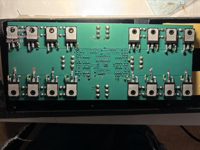
The power supply arrived last Thursday as did the smaller gate resistors. I fitted the fets to the second power board with the smaller resistors. Following Wiseguy's test procedure everything checked out ok on the bench with both boards, hooked up to the toroid and all was good (both power boards and both nano boards were tested and all worked). I guess it must have been an unstable supply coming from the batteries and light globe or fuse when loaded with the toroid after all. I'm happy to be the village idiot if it saves someone else from making the same mistake!
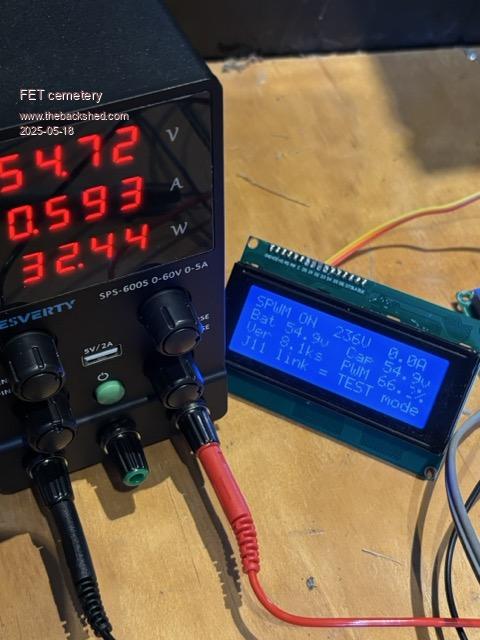
Eventually wound it up to 54V in, 235V out, this is with the nano board and fet board powered by the variable supply: The transformer makes a nasty hum if the voltage is wound up too fast but settles down pretty quickly.
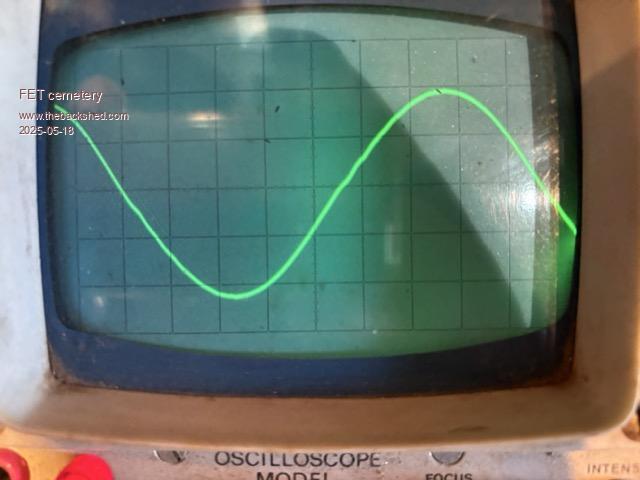
Waveform is ok.
Couldn't help myself, I hooked it up to the house battery with a 32A breaker on the DC side and ran a 1kW heater for 20 minutes or so, bit of a hum from the transformer and the waveform wasn't as pretty but this was using the power board with the big resistors and some fairly untidy wiring that could easily have been picking up switching noise.
The bias supplies and regulators were slightly above ambient, 5 degrees or so, nothing else was even remotely warm. No air movement, power board lying flat with the heatsink underneath it.
Efficiency was a whisker under 95%, take away the 30W standby power and the conversion efficiency is nudging 98% at 1kW. Impressive!
Time to build a cabinet for it and wire it up properly.
Thank you to everyone who has helped me get this far!
Posted: 09:06am 18 May 2025 Copy link to clipboard
KeepIS Guru
Those little power supplies are worth every cent when building this stuff. You might want to get the PWM% idle up a tad, but see how it goes, certainly looking good though.
Posted: 09:54am 18 May 2025 Copy link to clipboard
FET cemetery Regular Member
Yep the PWM does seem a bit low but it'll be spending a lot of time over 5kW so will leave it for now and see how it behaves under load.
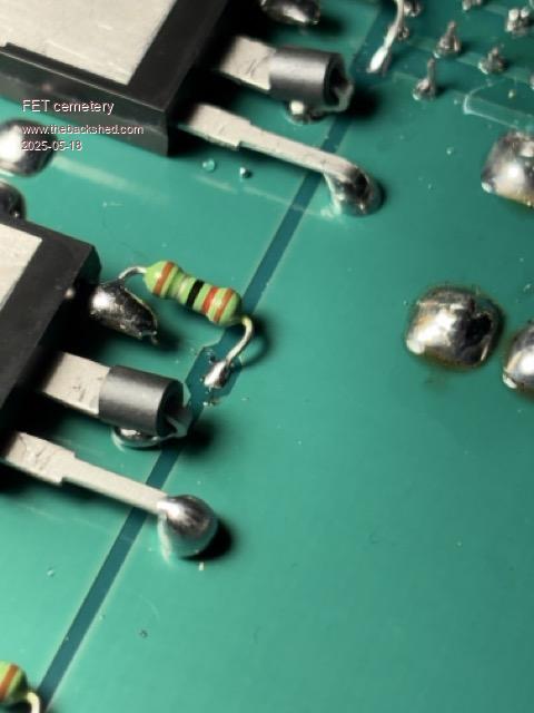
I used a different technique soldering the fets on the second board:
The drains and sources were soldered from the component side using the unregulated 80W iron. The fets were pushed up against the heatsink to keep them cool, and the iron was held on the leads for 8 to 10 seconds, getting both sides of the board hot enough for the solder to melt all the way through:
I'm pretty happy with the result, will do the same to the first board when I swap the gate resistors.
Posted: 03:37am 09 Dec 2025 Copy link to clipboard
FET cemetery Regular Member
Well it's taken ages, other stuff gets in the way, but the inverter is finally up and running. Not complete mind you, there's some tidying up to do, ok there's a lot of tidying up to do (the toroid is still not in the case, fans are switched manually) but it's running.
I am seriously impressed, this is a properly powerful machine. At 3.6kW it barely gets warm with no fans. Charging the car at 5.7kW, again with no fans, the heatsink gets warm and the pcb slightly warmer, not more than about 20C above ambient. Turning the fans on, the heatsink runs cold with minimal airflow and the pcb is a bit warm. The toroid seems to run cooler than with the egs002/powerjack board at the same output, 3.6kW doesn't need a fan and anything more needs minimal airflow to keep things cool.
A couple of questions-
At idle, pwm is 68% (54V in). I have to run at 5.7kW and let the battery drop to 47V (something that would never happen normally) to get pwm up to 85 or 86%. Would losing a turn off the 12 turn primary be a good idea?
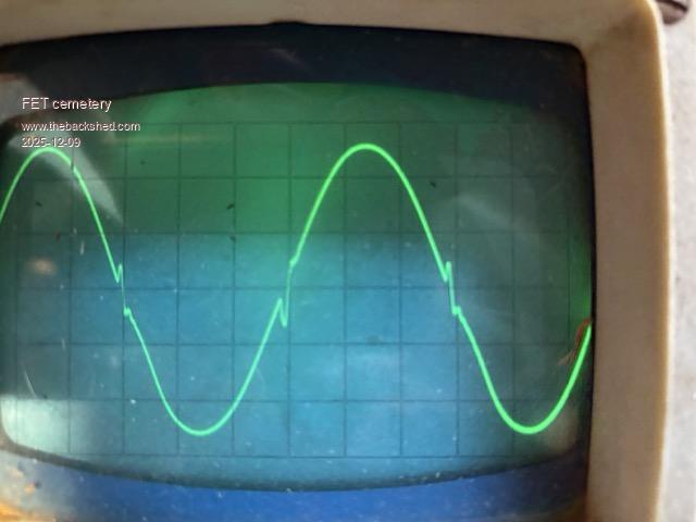
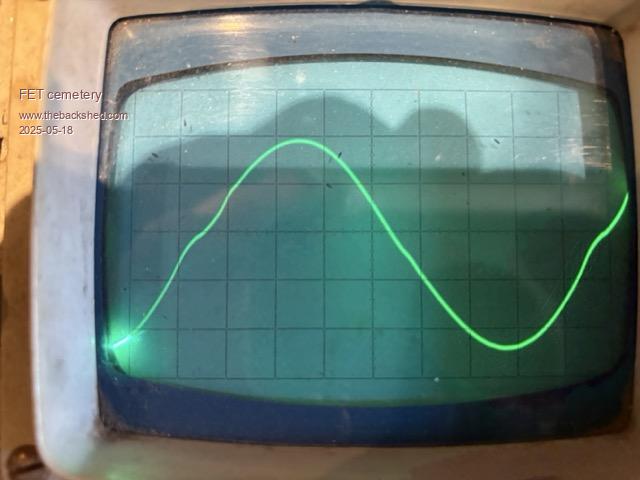
There's quite a buzz/hum from the transformer when charging the car, regardless of the charge current. This was the case with the powerjack board as well. On the scope the output looks interesting:
This was at 5.7kW, it doesn't look much different at 1.5kW.
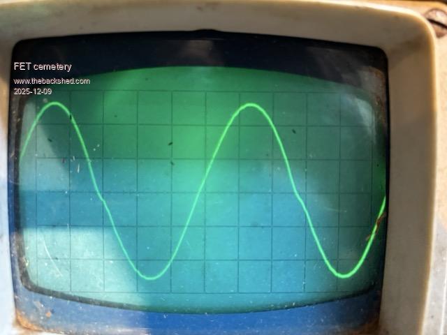
For comparison, this is the inverter running 1.5kW into a old box-in-the-wall induction motor aircon:
I don't think there's anything wrong with the inverter, I suspect it's an interaction between the car's internal charger and the big toroid. I'm picturing some sort of big switchmode supply that abruptly stops drawing current just before the zero crossing, with the spike in the waveform being the toroid reacting to that. Could be completely wrong, interested in what others think.
Does this matter, and can anything be done about it?
It's early days, but the inverter doesn't seem to run any hotter charging the car than it does with a purely resistive load (of course my IR thermometer packed it in a couple of months ago). Have yet to use it to run the 3.6kW kiln, will look at the output waveform when I do.
Once again, thanks to Wiseguy, KeepIS, Poida and all who have contributed to this project!
Posted: 04:45am 09 Dec 2025 Copy link to clipboard
KeepIS Guru
That distortion is likely the Car charger, the only thing it causes is a buzz in the Toroid.
I monitor some horrible loads via the two Peak DC input current meters and the DSO, there has been no increases in input current with loads far worse.
IMHO 68% is on the low side, checking with an input turn removed might be a good idea, as the FETS work harder with a low duty cycle and high power, mine is around 73% at idle, and I think I should remove a turn as well, but it's working perfectly so maybe in the future.
I've often running at over 14kW and the SPWM is around 88% from memory.
Great to hear the update.
Posted: 04:46am 09 Dec 2025 Copy link to clipboard
KeepIS Guru
That distortion is likely the Car charger, the only thing it causes is a buzz in the Toroid.
I monitor some horrible loads via the two Peak DC input current meters and the DSO, there has been no increases in input current with loads far worse.
IMHO 68% is on the low side, checking with an input turn removed might be a good idea, as the FETS work harder with a low duty cycle and high power, mine is around 73% at idle, and I think I should remove a turn as well, but it's working perfectly so maybe in the future.
I've often running at over 14kW and the SPWM is around 88% from memory.
Great to hear the update.
Posted: 05:05am 09 Dec 2025 Copy link to clipboard
FET cemetery Regular Member
Thanks KeepIS, I figured it was nothing to worry about but it's good to have another opinion.
I will remove a turn from the primary and see how it goes.
Tempted to run to higher outputs, but I software limited the car charger to 24A when it was installed to avoid inadvertently blowing up the powerjack board and it's fed through a 25A breaker. I will change this eventually, the charger can run 32A/7.2kW, but there's no rush.
Posted: 05:28am 09 Dec 2025 Copy link to clipboard
KeepIS Guru
In fairness, need to keep in mind that when I'm running at 14kW, each power stage in the inverter is only running at 7kW
It's only the batteries and solar chargers that would feel any strain, and apparently, they don't have any problems at all.
Posted: 09:10am 09 Dec 2025 Copy link to clipboard
nickskethisniks Guru
Doesn't removing a primary turn lowers the dutycycle further? The ratio increases when you remove a primary turn.
Posted: 11:07am 09 Dec 2025 Copy link to clipboard
FET cemetery Regular Member
"Doesn't removing a primary turn lowers the dutycycle further? The ratio increases when you remove a primary turn."
You're right of course, had to think about it a bit then confirmed it experimentally!
Idle duty cycle went from 72% to 78% with an extra turn added to the primary (night time here, battery at about 50.5V). Will tighten the primary winding up a bit tomorrow and see how it goes charging the car.
Posted: 10:08pm 09 Dec 2025 Copy link to clipboard
KeepIS Guru
Correct, I'll just blame old-timers kicking in.
Posted: 10:12pm 09 Dec 2025 Copy link to clipboard
KeepIS Guru
That's much better, interesting to see what % is now under a good load.
Page 7 of 8
The Back Shed's forum code is written, and hosted, in Australia.


 Those little power supplies are worth every cent when building this stuff. You might want to get the PWM% idle up a tad, but see how it goes, certainly looking good though.