| Menu | JAQForum Ver 19.10.27 |
| Menu | JAQForum Ver 19.10.27 |
Forum Index : Microcontroller and PC projects : PicoMite V6.02.00 release candidates - Structured types
That was just proof of the syntax when his example had errored out. |
||||||
There have been programs written in BASIC that accept inputs from the user then, based on that data, write a BASIC program to disk as an ASCII file with a .BAS extension. That stand-alone file can then be run directly or imported and tokenized depending on the target system. The ASCII file is comprised of various sub-sections read in from disk then modified before being written out to the new file. This means that the entire new file is never held in memory. Not all the auxiliary files will be needed in every case so the system can be pretty flexible. Could that be done here? |
||||||
JanVolk PicoMite.zip Please try this debug RP2350 version. I've made some defensive changes when an i2c is being used both for foreground tasks and also in the background. I've temporarily changed the rtc update rate to 1 minutes and everytime is runs it will print a 'r' to the console. As before this runs indefinitely for me with your program. Let me know if this makes any difference for you. You should see a lowercase r every minute while your program is running. |
||||||
@Peter, Please note that system I2C can also be used by WII and NUNCHUCK controllers. And this operates at a repeat rate you defined. Maybe that is related. I did not see any problems with RTC and WII controllers on RP2040, but maybe 2350 is different. Especially with the GPIO hardware bug in the chip. You cannot rely on weak internal pullups, you need strong pullups (4.7k or lower). Most RTC already have 10k or 4.7k pullups on the board. Volhout |
||||||
I'm assuming Jan knows this stuff. There were issues with background tasks like WII and Nunchuck interacting with foreground I2C activity which are addressed in the latest RC and which I have strengthened further in this version. For example, if a foreground task used the option to hold the bus and a background task ran between the hold and the release bad things could happen. |
||||||
Peter and Harm, I've done some more research since my last post. The RP2350A is a model with 16MB flash. I did a fash_nuke yesterday, and the firmware ran for 1.5 hours without any problems. This morning I set the autorun option to on, after which I had some startup problems, such as the backlight going off. Then I set the pause time from 500ms -> 5000ms, and it's been running for 1.5 hours without any problems so far. I just downloaded the latest RP2350 update (picomite.zip) and it's now up and running. I do indeed see an "r" appear on my TeraTerm console screen every minute. It's also working fine on the LCD2004 screen. I'm using a MAKER PI PICO with the RP2350A module. On the right side, I've mounted a 4x20 LCD2004 screen on nylon bushings, and on the bottom of the LCD, I've installed a standard I2C to parallel module for these screens. I solved the 5V bus problem by using 2x4k7 pullups from 5V to 3V3. Underneath the MAKER PI PICO is a DS3231 module with EEPROM, all on the same bus. Because the 4k7 resistors are in parallel, the resistance is already lower. Ten years ago, I created a greenhouse controller for a hobby greenhouse with various sensors using an Arduino nano and BascomAVR, which has always worked without any problems. Last year, I had some problems with the 24V power supply, and now I've made everything 5V, and the rain sensor is showing signs of wear on the sensor surface. I'm trying to get this controller, using the same sensors, to work with the PicoMite as well. The controls are operated using three keys: UP, DOWN, and ENT, and sensors include two DS18b20 sensors, a 10K window potentiometer, and a rain sensor. All 22 settings were then written to the EEPROM in the nano. Now that I'm typing this, I get a message on the terminal. > run rrrrrrrrrrrrrrrrrrrrrrrrError: Invalid address - resetting > rrrr The program is still running because the r's are being filled in, but the time on my LCD2004 has stopped. (18 r's already added) So the problem is with the I2C connection/software? Kind regards, Jan. |
||||||
Your code ran all night for me without a display connected (standard Pico2) which suggests to me something electrical may be at play. Are you running the I2C bus at 5V? Will the display run at 3.3V. If it will try everything at 3.3V. Have you disabled the LEDs on the Maker Pi (unsolder jp13)? This feels instinctively wrong but.... More thoughts. If the display will only run at 5V uses a level changer. You do know that the RP2350 is only 5V tolerant when powered? DO NOT power the display without the RP2350 also powered if using 5V Edited 2026-01-14 23:02 by matherp |
||||||
Peter, The I2C runs on 3V3. The DS3231 already runs on 3V3 by default, and the display receives its 5V supply via a separate PCB. The bus board on the back of the LCD normally operated at 5V with pull-ups SDA and SCL to 5V. I desoldered these two SMD resistors, connecting the SDA to 3V3 and the SCL to 3V3. (Could it be that the pull-up SMD resistors were removed because the RTC already has pull-up resistors?) These resistors are also in parallel on the DS3231. I made a modification on the MAKER PI PICO. I cut the path that powers the LEDs, and on the PCB, I repurposed six unused pins that I don't use. I cut the SWCLK track, and connected the pin to one of the positive pins on the LEDs. Now I can use a jumper to connect the 3V3 pin to the free pin, or the jumper to a pin that's off. This has been working without any problems for years. However, I'm using the LCD screen for the first time with an RP2350, and previously with an RP2040. Is it possible that the pulldown problem with an RP2350 is causing the problem here? I can try making the pullup values of the sda and scl smaller, so smaller than 4k7 which are on the DS3231 because those of the lcd are no longer present? Kind regards, Jan. Edited 2026-01-14 23:36 by JanVolk |
||||||
No: E9 doesn't affect I2c or spi operations of the pins |
||||||
I found an lcd display off an old 3d printer so I have duplicated your environment and am letting it run with the debug version of the code that outputs the 'r's. The only difference is that I am using proper level conversion on SDA and SCL. I'll leave it running and see what happens. Currently running standard system I2C (not slow) 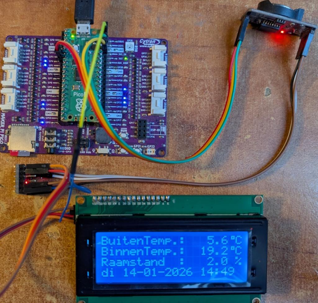 |
||||||
@Jan, PCF8574(A) is 5V I2C (Vh minimum is 3.5V) 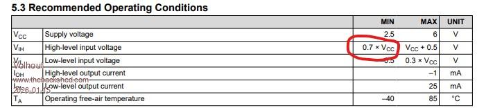 PCA8574 can work with both 5V and 3.3V levels at I2C DS3231 is 3.3V I2C Pico 2 in essence is 3.3V I2C, but can survive 5V under certain conditions. I hope you are driving the chips at correct levels. I see in Peter's photo he uses a level shifter between pico and PCF8574. That is correct. Volhout Edited 2026-01-15 01:46 by Volhout |
||||||
Thanks for all your attention. I first measured the pullup resistor of the SDA and SCL on the connection pins, and it's 4K7. Then I added a 4K7 pullup to the free SDA and SCL pins of the DS3231. (The value is now 2K4.) The program started and now works flawlessly on the terminal with rrrrrrrrrr and on the LCD2004. I still have a few 2-channel I2C level shifters (they have 8 pins), so that's the next step if this test fails. It's been working flawlessly for over 2.5 hours now. What is noticeable during autorun is that the program doesn't start automatically the first time, the RTC auto-enable option has disappeared from the list, and the backlight turns off on startup. Once it's started with the RTC auto-enable option, the backlight works correctly. And regarding the power supply on the PCA8574(A) type, it's 5V. The A type has an extra set of addresses, both of which I have. Only the SDA and SCL are connected externally to a 3V3 pullup. I'll wait and see about this test. Kind regards, Jan. |
||||||
@matherp Hi Peter, I found code for implementing HDMI audio on the RP2350 HSTX (High-Speed Transmit). Maybe PicoMite will someday also have an HDMI audio option? https://github.com/fliperama86/pico_hdmi I should note that this signal isn't supported by older DVI monitors, but it works with modern monitors that have an HDMI port. |
||||||
Instead of layers, tiles, multiple resolutions? V6.02.00RC6 PicoMiteV6.02.00RC6.zip This release includes additional protections for avoiding interections between foreground and background I2C activity on SYSTEM I2C. In addition, because it was trivial, I've added a new command: I2CLCD Command Purpose: Controls HD44780-compatible character LCD displays via a PCF8574 I2C I/O expander module. These adapter modules are commonly found as daughter boards on 16x2 and 20x4 character LCDs, providing I2C control using only two wires (plus power). Syntax: I2CLCD INIT address I2CLCD CLOSE I2CLCD CLEAR I2CLCD BACKLIGHT state I2CLCD CURSOR state [, BLINK] I2CLCD CREATECHAR code, d0, d1, d2, d3, d4, d5, d6, d7 I2CLCD CMD byte [, byte ...] I2CLCD DATA byte [, byte ...] I2CLCD line, position, string$ I2CLCD line, Cn, string$ Description: Subcommand Description INIT address Initialize the LCD at the specified I2C address. The address is typically &H27 or &H3F for most modules. PCF8574 uses &H20-&H27, PCF8574A uses &H38-&H3F. Requires OPTION SYSTEM I2C to be configured first. A degree symbol (°) is automatically created at character code 0. CLOSE Close the LCD and turn off the backlight. CLEAR Clear the display and return cursor to home position. BACKLIGHT state Turn the backlight on (1) or off (0). CURSOR state [, BLINK] Control cursor visibility. State can be ON/OFF or 1/0. Optional BLINK parameter (or 1) enables cursor blinking. CREATECHAR code, d0-d7 Define a custom character at code (0-7). The 8 data bytes (d0-d7) define the 5x8 pixel pattern, with each byte representing one row (values 0-31, only lower 5 bits used). CMD byte [, byte ...] Send raw command byte(s) directly to the LCD controller. DATA byte [, byte ...] Send raw data byte(s) directly to the LCD controller. line, position, string$ Display text on line (1-4) starting at position (1-40). line, Cn, string$ Display centered text on line (1-4). Cn specifies display width: C8, C16, C20, or C40. Hardware Configuration: The PCF8574 I/O expander must be wired to the LCD using the standard configuration: P0 = RS (Register Select) P1 = RW (Read/Write) P2 = EN (Enable) P3 = Backlight control P4 = D4 P5 = D5 P6 = D6 P7 = D7 This is the default wiring used by virtually all LCD I2C backpack modules. Prerequisites: The SYSTEM I2C interface must be configured before using this command: OPTION SYSTEM I2C sda_pin, scl_pin Example: ' Initialize LCD at address &H27 I2CLCD INIT &H27 ' Display text I2CLCD 1, 1, "Hello World!" I2CLCD 2, C20, "Centered Text" Pause 5000 ' Show temperature with degree symbol (auto-created at CHR$(0)) I2CLCD 3, 1, "Temp: 25" + Chr$(0) + "C" Pause 5000 ' Create custom heart character at code 1 I2CLCD CREATECHAR 1, &B00000, &B01010, &B11111, &B11111, &B01110, &B00100, &B00000, &B00000 ' Display custom character I2CLCD 4, 1, "Love " + Chr$(1) Pause 5000 ' Control backlight I2CLCD BACKLIGHT 0 ' Off Pause 1000 I2CLCD BACKLIGHT 1 ' On Pause 1000 ' Show cursor with blink I2CLCD CURSOR ON, BLINK Pause 5000 ' Clear display I2CLCD CLEAR ' Close when done I2CLCD CLOSE Custom Character Design: Each custom character is defined by 8 bytes representing rows 0-7 from top to bottom. Each row uses 5 bits (values 0-31) for the 5 pixel columns: Row bits: &B00000 = ..... &B11111 = ##### &B01010 = .#.#. &B10101 = #.#.# Line Addresses: For multi-line displays, the DDRAM addresses are: Line 1: Address 0 (0x00) Line 2: Address 64 (0x40) Line 3: Address 20 (0x14) Line 4: Address 84 (0x54) See Also LCD, OPTION SYSTEM I2C Edited 2026-01-15 05:46 by matherp |
||||||
Peter, This is a really nice addition to the firmware, I2CLCD, which I've been looking forward to for a while so we no longer need the subroutines. I have a lot of these displays from the Bascom and Arduino era, and perhaps I'm not the only one? They only require two pins for an I2C bus. I haven't tested it all yet, but it runs concurrently with the LCD command, which requires many more pins and also requires a level shifter. Another question: Can I2CLCD be used alone or in conjunction with other displays? I've already loaded V6.02.00RC6 into an RP2040 and will start working on it tomorrow. Thanks in advance. Another question about the I2C EEPROM on the DS3231 module. Can this be included in the firmware so we can write and read from this chip as a backup? The modules are very inexpensive. But what do others think about this, or have they been overtaken by flash? See the System I2C list, where this EEPROM is also listed. The EEPROM subroutine looks quite complicated. Perhaps it would slow down the rest of the firmware too much or take up too much space? The program (picomite.zip) is still running flawlessly for me as of this afternoon with the lowered I2C bus resistors, which is already fine. I'll check if automatic startup and removal of the RTC auto-enable option still occur, and if not, test it with a level shifter. Otherwise, we have two methods for an I2C bus with the LCD2004, but not everything has been tested yet. Kind regards, Jan. |
||||||
I also have a few questions about LCDs with HD44780 and compatibles: I have about 10 "brand new" MDL(S)-24119 LCDs (with a parallel interface) – they can display 1 line x 24 characters and also have an HD44780-compatible controller. They were either thrown away at work or left out for anyone to take (long ago).  Is this also supported by the 'LCD' command?  How does the HD44780 'LCD' driver in MMBasic know how many characters per line to display? Could this be passed as an optional parameter to the 'LCD INIT' command? Perhaps also the number of lines? They're handy; you could make a calculator like the SHARP-PC1403 with them... Kind regards, bfwolf |
||||||
bfwolf, It all works automatically. Here I'm using a 4x20 screen. See the program list. I'm using a level shifter between the RP2040 and LCD2004. With I2CLCD: y, x 'y = Line number, x = Character number, C = Center. PicoMite MMBasic RP2040 V6.02.00RC6 Copyright 2011-2025 Geoff Graham Copyright 2016-2025 Peter Mather > option list PicoMite MMBasic RP2040 V6.02.00RC6 OPTION SYSTEM SPI GP10,GP11,GP12 OPTION SYSTEM I2C GP20,GP21 OPTION COLOR CODE ON OPTION HEARTBEAT OFF OPTION PICO OFF OPTION CPU SPEED (KHz) 200000 OPTION DISPLAY 50, 100 OPTION SDCARD GP19 OPTION F1 FLASH RUN 1 OPTION PLATFORM PicoMite RP2040-SD:32G > list I2CLCD INIT &H20 I2CLCD 1, C20, "Hello world!" I2CLCD 4, C20, "Love" > run Kind regards, Jan. Edited 2026-01-15 10:58 by JanVolk |
||||||
Some time ago I'v written a few routines to store/retrieve variables from MMBasic into I2C EEPROM on the DS3231 module. It supports integer, float and string datatypes on MMBasic side and you have to keep track of where you store it in EEPROM yourself. If you want I can post them here. Gerald |
||||||
@Peter: Hi Jan, The question is whether the (parallel) LCD driver or the I2CLCD driver can automatically know the number of characters per line? Is it possible that the 16x2 LCDs use the same display RAM configuration as the 20x2 displays, but the last four cells are simply not used? The HD44780 has display RAM for 80 characters. This can be used for 80x1, 40x2, or 20x4, or indeed for 24x1, 16x1, or 16x2, etc. There are even 8x2 displays with this controller. If the driver implicitly assumes that a maximum of 20 characters per line are used in the LCD, it would probably not accept characters 21-24 in the output of a 24x1 display? Or does it automatically write them to the cells behind them, so that it would work on a 1x24 display and on a 20x2 display there would be a line break in line 2, but on a 16x2 display characters 17-20 might be lost because they are in RAM cells that are not connected to the LCD? Of course, you can ultimately control everything with 'LCD CMD' and 'LCD DATA', but 'LCD line, pos, text$' might then work incorrectly. Kind regards, bfwolf |
||||||
The HD44780 has effectively 2 * 40 character buffers. All two line displays use the first n characters of each buffer for the two lines. As per my post, For 4 line displays each 40 character buffer is split Line 1: Address 0 (0x00) Line 2: Address 64 (0x40) Line 3: Address 20 (0x14) Line 4: Address 84 (0x54) The only oddity is a display with more than 40 characters in a line in which case the output is split across the two buffers which are non-contiguous and you would have to code round this. For 80x2 displays they use two separate controllers. Edited 2026-01-15 20:48 by matherp |
||||||
| The Back Shed's forum code is written, and hosted, in Australia. |
