  Page 9 of 14 Page 9 of 14   |
Posted: 07:45am
28 Dec 2024
 Copy link to clipboard Copy link to clipboard |
rogerdw
Guru

|
|
|
Good to see the progress Aaron. I used copper bar where I could ... especially for the short lengths where it would have been hard to get short cables to bend into place. I do like Phil's idea of stacking strips together ... bit easier to handle and flexible. The battery cable and Solar Charge controller leads come in via cable to the Kilovac ... then copper bar to the cct breaker ... and from the cct breaker to the main busbar 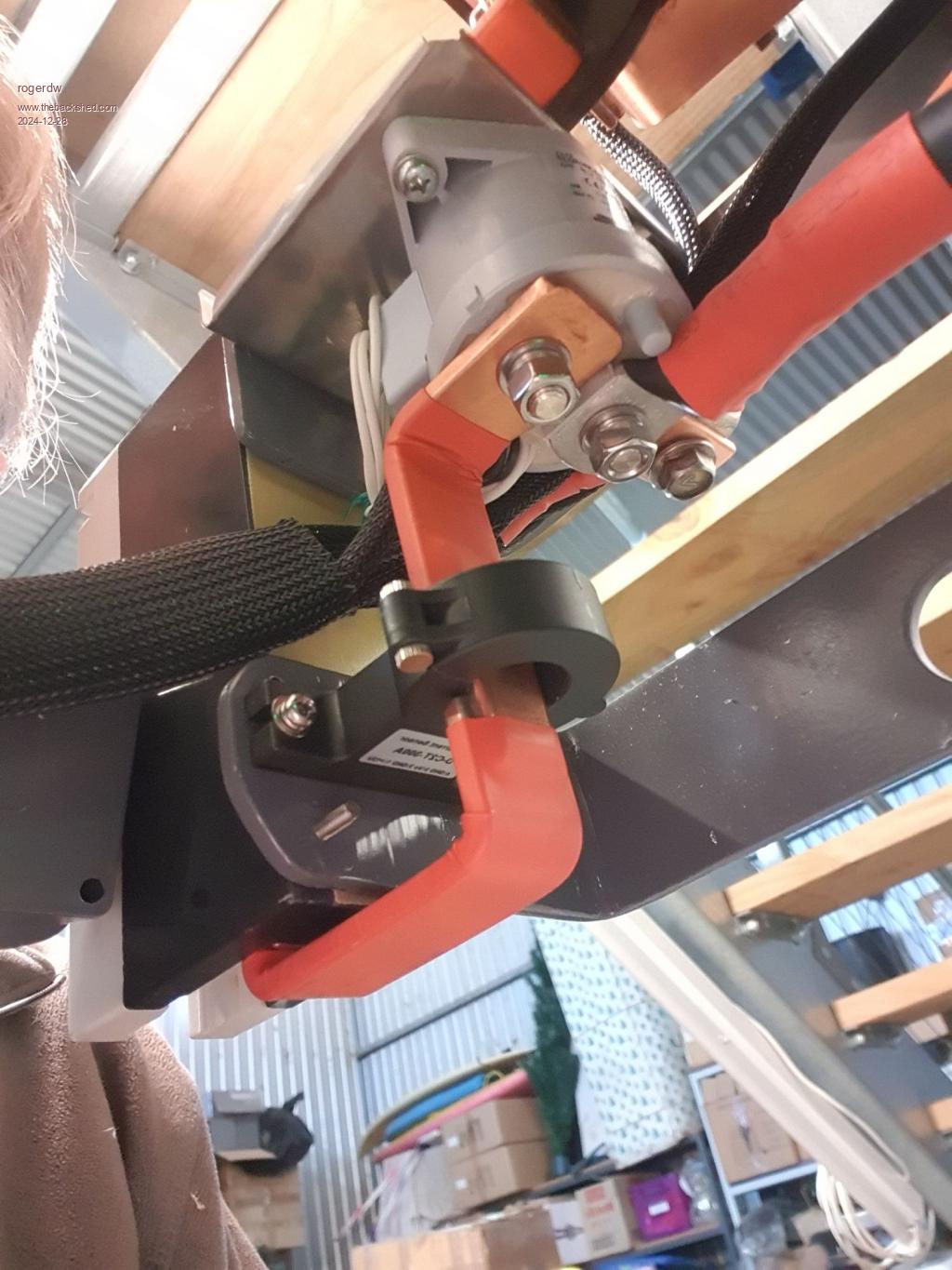 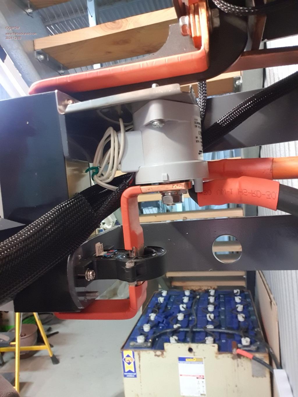 I got a bit carried away I think.  But it does tuck in nice and neat ... and it certainly doesn't get warm. 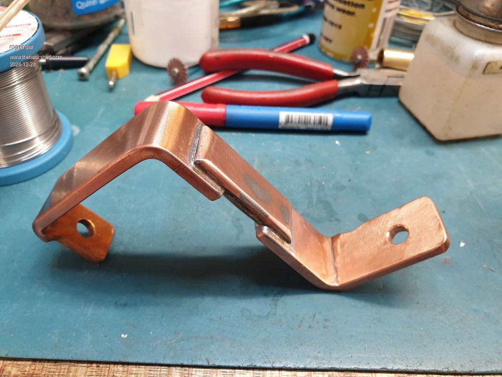 Edited 2024-12-28 17:54 by rogerdw Edited 2024-12-28 17:54 by rogerdw |
| |
Yeah I would also have preferred multiple layers of copper strip as its flexible, unless someone has soldered the end solid with a hole drilled through (pined) makes it hard to bend and will kink, but looks really good with shrink wrap over it. I may have some copper sheet in an old transformer but would have to cut into strips, will have a look later. I will be using the large flexible cable and crimped terminals going out to the chokes and transformer, but inside its such a short distance the copper bar seems to be the easy goto.  That looks Excellent, very neat Rodger,  that's about what I was thinking of, mostly trying to re purpose what I have on hand there is a few different size's of copper bar salvaged from large transformers, there is also a way of getting a 90 degree bend the other way by putting a 45 degree crease and fold over itself, I had success with thin copper like that but have yet to try some of the thicker stuff, will see what happens. Thanks guys for the encouragement and ideas. |
| |
|
The thick copper bar bends easily with a bench-vise and metal bending adapter, I bent the DC input copper bus bars in the Dual inverter and the main battery bank bus bars with one. |
| |
Bending thick copper bar is pretty easy now using a oxy torch just heat say 10mm each side of the intended bend red hot then let it cool which will anneal the copper making the bend nice and easy. Do it in a vice then by tapping with hammer will work harden it and just rinse and repeat for the other bends. |
| |
Posted: 06:44am
31 Dec 2024
Copy link to clipboard |
rogerdw
Guru
|
|
|
I'm no metal worker I'm afraid ... I just stuck those bits in the vice and wacked them with a big hammer. Wasn't hard to bend either, I was surprised ... but I'll keep that suggestion in mind for next time thanks Bryan. |
| |
Well it was fun, I have done plenty of metal work, some shrinking and stretching on the 25mm copper bar and it can be bent, the other 2 (transformer bus bars) are 1/2 by 1/8 (really old) imperial copper bar doubled up so its quite thick, still needs a few miner adjustments but should be ok. Now I have to find the heat shrink, its on a shelf last I saw it.  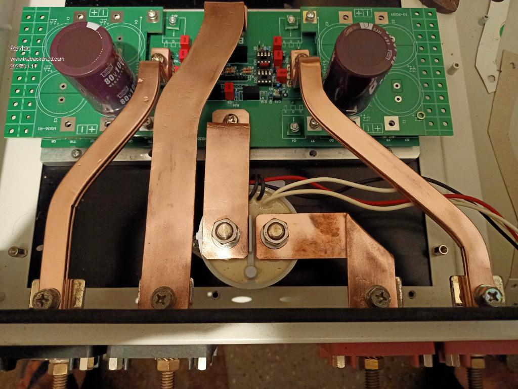 |
| |
Posted: 10:13pm
16 Jan 2025
Copy link to clipboard |
rogerdw
Guru
|
|
|
Great job Aaron, that's coming together nicely. There's something about nicely shaped raw copper that appeals to me.
It always seems such a pity we need to insulate it, and that it goes all tarnished after a while. I'm sure there's a few different clear coatings that would protect it but a thicker heatshrink is still probably more of a protection from accidental shorting.
You must be getting close to fire up time soon. |
| |
Yes its nice all polished up but doesn't stay that way, (I have a few old engines that have brass and copper parts looks very nice) I was looking at your build photos last night (very nice) reminded me of the old 300A 3 Phase Breaker panel I have. I have the bars covered in heat shrink now and build is progressing nicely when I get time, the filter board is the original GTI but it might be over kill, I could just bridge some of it under board if needed but would like to keep the MOV's in place, must remember to put a screw in there for earth. The front panel will take a little metal work and time later. 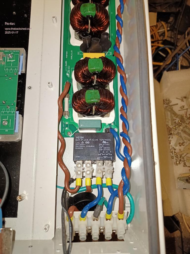 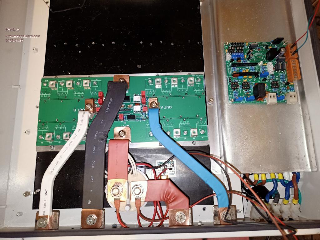 Footnote added 2025-01-23 20:38 by Revlac Footnote added 2025-01-23 20:38 by RevlacThe SMD FOD3182 were nice to mount on the little pcb's supplied. |
| |
Posted: 11:40am
20 Jan 2025
Copy link to clipboard |
-dex-
Senior Member

|
|
|
Hi, your copper connections look really solid. If I were a one of final MOSFET I would be afraid  If I can make a suggestion at this stage, it is where to place the driver board. When you place this near cables with high impulse currents flowing, expect noise and interference around that may want to disrupt the operation of your controller - that was my experience. In my build, noise was causing interference in the AC feedback voltage measurement, which resulted in poor performance of this circuit, AC voltage was dropping too much during when inverter was operating with loads. Place it further away, or put it in a metal box, and I'm not sure if being close to an EMI filter would also interfere. |
| |
Hi Dex, I remember reading about the noise and interference and thats why I shifted the control board to the side, The plate the control board sits on will be grounded in hope that it works, if not I can add another level of shielding there, Thats part of the fun building this stuff...... Thanks for the reminder. |
| |
Yes, I agree with Dex that the location of the driver board is important for good AC voltage regulation - as I found out the hard way . Another suggestion, rotate the driver board so that the two Op Amps are furthest from the bus bars. Also, I assume that your enclosure is grounded to the AC mains. I grounded the control board shielding to DC ground, which is *not* connected to AC ground in my inverters. |
| |
Yes, I intended to use AC ground, same as most other things are, I still have the option to ground either way or more shielding and rotate the PCB, the 8 pin cable is plenty log enough..... Clockwise 1/4 turn. Ok, I Rotated the pcb, and I like it better. 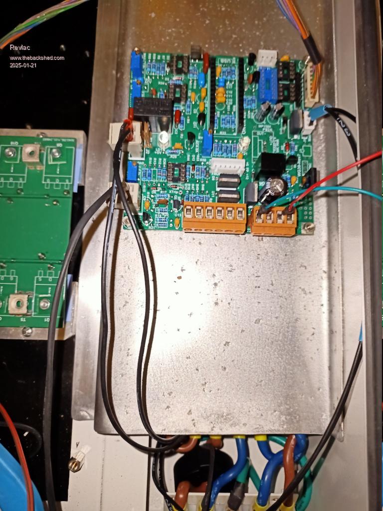 Those little stand off bolts on the corners of the PCB are taken from the computer PC Cards, com ports they are a good size but didn't find many nuts to suit the threads on them. |
| |
Had to have a little bit of 3D printing in this build......Because I Can........Made it easy to mount the LCD to the existing studs on the front panel, seems to be a firm fit without any screws so far. Made a bezel around the front screen, it was just a quick rough print using a 0.8mm nozzle in draft mode, pretty rough print as it was good for a design test fit, still have to drill holes for the 3 LED's not sure weather to include them in the bezel under the screen. I will mount the on/off and reset switch somewhere down the bottom as we shouldn't need to use them much. 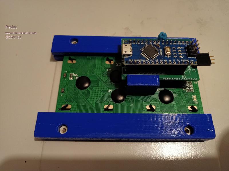 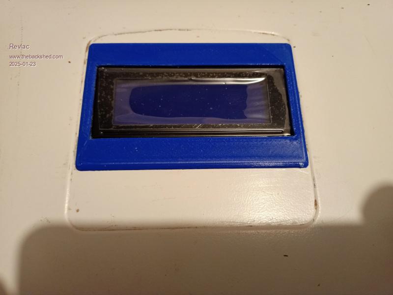 |
| |
Bit more done, always find a few more things to do each time I check it over, its not far off powering it up on the bench for a check, already powered the board without the IC's in place and the voltage regulators are ok up to 48v (thats the power supply I had) and it needs a final wiring check. Likely a few other things I haven't done yet, making a wiring harness (cable management) look neat has never been one of my strong points. 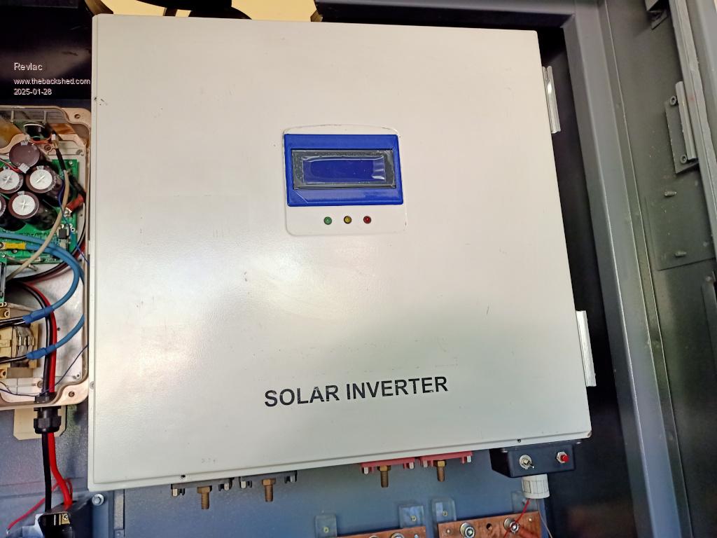 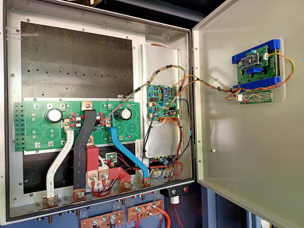 |
| |
|
Looking really nice, are they your test cap boards with fiberglass washers still intact?
How many caps are you planning to use, reason I ask is I found I needed a minimum of two large high ripple current screw terminal caps on each cap board to reduce cap heating to a minimum when running above 4kW on a single power board for long periods of time.
I really should have purchased 4,700uf Caps in order to keep the total capacitance per power-board around 20,000uf to 30,000uf, mine are 10,000uf caps.
. |
| |
|
Thanks, they are the test capacitor boards (Excellent idea too) and small test caps to start off, though I now think the 560uf test caps is an the small side for testing, had some bigger ones 1000uf on the bench but the seem to have rolled off somewhere, that happens when things are round.
Those Fiberglass washers were handy I used a few more of them under the large terminal mounts to allow more gap between the back plate and the case.
I was thinking of using the 10 000uf caps I have 3 per cap board and a smaller value or 2 big ones and 2 smaller ones depending on what I find, from reading other post probably don't need a lot of capacitance there. |
| |
|
Yes, being able to swap in small test cap boards is really handy during the initial testing.
My initial power up (in test mode) is with a current limited adjustable power supply and 100uf on each cap board, if I get to 16v and there is no AC output, I stop.
FYI, I carried out a lot of testing with cap values, I found a total of 10,000uf on each cap board (20,000uf total) was around the sweet spot with respect to Inverter stability, adding more capacitance made very little difference past that value to noise, waveform quality and harmonic output.
Four large 2,200uf to 2,700uf caps per board would be a good choice, but good quality caps with high ripple current are around $30 to $50 each from quality AU suppliers.
I quite often use reclaimed caps, so unknown ripple current and quality may not be up to the task at high power levels, the main thing is monitor cap heating at higher power levels and avoid excess heating. |
| |
Ok, I have a current limited bench power supply that will only go to 30v but looks like it will be capable of a safe startup and see if everything is working properly. did look for some more capacitors today and found a few so might use some of them along with the some new ones. Bit of a surprise the price of those screw in ones, not so bad if we only one was needed for a one off job, I just looked at the caps on the Latronics PV Edge inverter and some are swollen not good so not using those  Probably be the weekend or later before power up too many things on my plate just lately, |
| |
Ok, its fired up and running, I did have the 2 zener diodes (D5 and D6) in backwards......it don't work like that, nothing damaged though. Only 1 toroid and its temporary wiring till I get the second one in and the some fans and a few other power meters etc, the sinewave is great with a light load 200w running all of today and still running the pair of test caps. The inverter at idle is about 14w but that will increase when the other toroid is installed, still need to do some calibrations, did a little already but had a few issues with the laptop and the Arduino IDE not getting along, will try a different terminal later. There is still one issue to resolve, will figure that out shortly, apart from that, Very pleased with the way its designed and works. 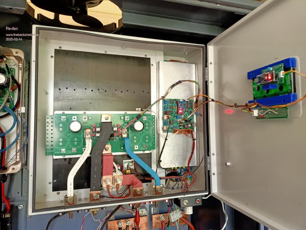 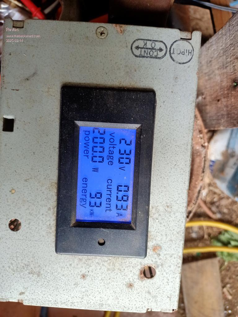 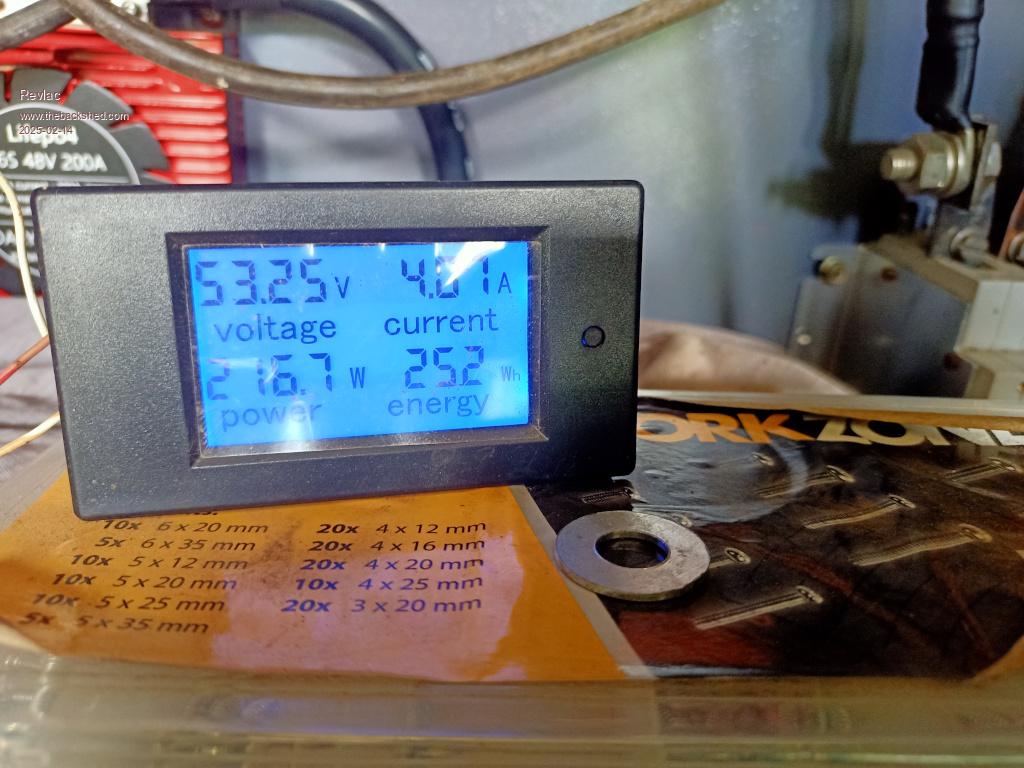 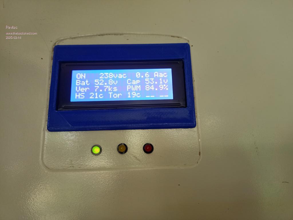 Ignore the 54Hz frequency on the little scope, it often has its own opinion. 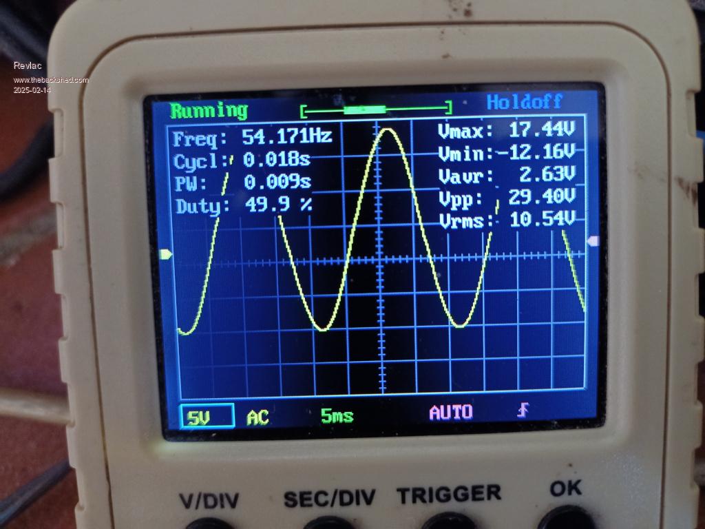 Footnote added 2025-02-16 23:47 by Revlac Footnote added 2025-02-16 23:47 by Revlac"I did have the 2 Zener diodes (D5 and D6) in backwards" To put it bluntly, I mistaken the K marking on the version 2 power board for the diode symbol direction.  |
| |
Great work, and no smoke let out Definitely needs a real terminal program to run correctly, one of the download files has the setup for TeraTerm and Yat. TeraTerm is very simple. |
| |
| Page 9 of 14 |

