| Menu | JAQForum Ver 19.10.27 |
| Menu | JAQForum Ver 19.10.27 |
Forum Index : Electronics : Turning a Toyota Prius into a "portable" generator
When opposite pairs of the h bridge were permanently on, wouldn't the DC breaker trip? I'm still waiting on the Hi-Link 15v smpsu's to come in. It's been 3 months! |
||||||
It sure will. But the question is, before or after your silicon turns into noise and smoke. IGBTs are vastly more robust than Mosfets. |
||||||
"IGBT's are vastly more robust than MOSFETs." They sure are! And I'm using 200v DC so the 1 to 2V drop isn't an issue, percentage wise. Well finally my Hi-Link 15v power supplies have come in so I can start designing the power PCB electronics. 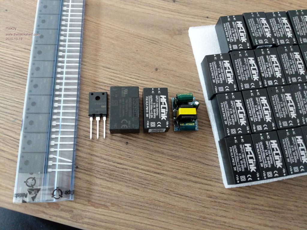 I did get some of the other cheap generic 12V power supplies to modify to 15v, but there was so much solder splatter on both sides of the PCBs that I didn't trust them enough to put into what will otherwise be a very robust inverter. Also since I'm designing a PCB I don't want to lock myself in to a footprint that will change based on their availability. The pic shows a comparison between the Recom, Hi-Link, and generic power supplies. Price wise, they are $30, $3, $2 respectively. I opened up the Recom and the Hi-Link to take a look inside. Both look like they are made from very good quality components. Both are in a silicone resin so it's hard to see everything. One thing I noticed is the Recom uses 2 X 3.3uf 450v rated capacitors but the Hi-Link uses a 400v labelled single 6.8uf capacitor. So the Recom is a slightly bigger package overall, and with a UL rating, you know you will get some good quality product. But for $30 each from RS, it was too costly given I need 16 of the little fellas. I'll go with the Hi-Link ones for this design. Now on to the IGBTs again! I was going to use some 3 phase IGBT modules but have now decided to go with discreet components. Namely 12 x IKFW90N60 IGBTs for the first 3 inverters and 4 X IXGN320N60A3 for the biggest inverter. The IKFW90 is an INSULATED TO-247 package that can handle some decent current.  Now can any engineers tell me why there are two separate current ratings at 65 degrees? And why the current rating is higher at a higher temperature? The footnote doesn't make sense to me.... I have already bought 20 of them, so I hope they will be ok. I bought them from mouser at $12 each, so I'm assured of their origin and quality. Come to think of it, what if I used the IKFW90 for all 4 of the inverter stages. Would I be able to plug in a 10A arc welder to the inverter and use it reliably? What headroom do any of these numbers really need? The switching speed is going to be nice and slow, and assuming a decent heatsink, there is a lot going our way. But trusting the numbers is an issue for me. To recap, I'll be using this inverter on a 200VDC Prius pack, and the largest transformer will be an unmodified aerosharp 3kw. I want to use it for heavy loads. Air compressors, table saws, that sort of thing. |
||||||
You would need to get the Infineon data book. Somewhere in that it will explain exactly how the device is tested, and what all the various abbreviations mean. But basically mosfets act like resistors when in the on state. Power and heat production rise in proportion to current squared. Under fault conditions, there will be an explosive release of heat which can be pretty fatal. Also the Rds on increases with temperature. As you work them harder they become slightly less efficient. Mosfets are excellent devices, but fragile. IGBTs on the other hand have a fairly constant voltage drop when turned on (rather like a diode). Power and heat production increase roughly proportional to current. Under fault conditions the heat release is vastly less than with a mosfet, so the device can handle short term overload much better. The on state voltage drop decreases with temperature, so as you work them harder they increase very slightly in efficiency. I have built many Warpverters of various types over the years, with both mosfets and IGBTs. I have blown up a lot of mosfets, mainly through stupidity and clumsiness. I have only ever had two IGBTs fail unexpectedly, and not from overload. Both were from the same batch, and both went open circuit, which is very unusual and appears to be a Chinese quality control problem rather than a shortcoming in the desigin or from abuse. I have used my warpverter with all kinds of power tools, compressor, 300mm cut off saw, 2Hp airconditioner etc, without any problems. Have tripped a 20 Amp curve C circuit breaker many times without any effect on the Warpverter. Don't own a stick welder, but it should (?) be ok, but never tried one. I have a 300 amp three phase MIG, that I run off the grid. Any of the modern Chinese switched mode MIG/TIG welders should be o/k too. The reason its so robust is that it can handle highly reactive and very distorted loads. Even at the zero crossing it can handle full peak current reflected back to the dc source. A pwm inverter will really struggle to do that. |
||||||
It's going to be tempting to do an empirical stress test with a few spare IGBTs on hand when I'm done.   |
||||||
Go for it |
||||||
Just a quick update on my journey and a question about transformers: Since I am looking for a compact design that will fit in the boot of my Prius, I opted to go with a custom PCB design that has all 4 inverters onboard. I'll go with IKFW90N60 IGBTs for all inverters. I've also sourced the same heatsink profile as used in the popular egs002 based inverters, so the final board will look very similar to, but will be functionally very different to the typical eBay type inverter boards. Question about transformers: Say I have a typical commercially available toroidal transformer, say 300w, 240v primary, 50v secondary. Without measuring the core dimensions, would it be a fair assumption that the saturation voltage of the core would be just over 240x(sqrt 2)= 340V on the primary side? |
||||||
Transformer saturation depends on only two things. The AVERAGE voltage across the winding each half cycle, and the time the voltage is applied (frequency). With a sinusoidal voltage waveform, its the average (0.637 x peak) not the rms (0.7071 x peak. With a square wave inverter like the Warpverter its the full applied dc rail voltage times the on time each half cycle. This gets complicated, because none of the voltage waveforms applied to the transformers are actually sinusoidal. But if the transformers are all designed for a sine wave equal to the dc supply rail voltage, all four transformers will work fine, not saturate, and have low core loss. In reality NONE of the transformers work like that with a 50Hz applied sine wave voltage, But if all are designed for an rms sine wave voltage equal to the dc supply voltage, all of the other factors such as frequency, duty cycle , flux swing, and core losses will all take care of themselves. It hugely simplifies the transformer design. Interestingly, although all the transformer voltages are square waves, the transformer currents are sine waves! Its a very difficult thing to visualize. |
||||||
Right, so if using standard 240V transformers for all 4 inverters, I assume the largest inverter would have the longest on time, and would therefore be the limiting factor for the highest DC voltage, yes? My question asked another way would be: Can the maximum DC warpverter input voltage be calculated for all 240v AC transformers on the market without specifically knowing the core dimensions? (And if so, what is it) Basically I'm trying to figure out if a 240v transformer primary winding can be left unmodified when using a 360 to 400V DC Nissan leaf battery pack, in a warpverter design. Then I can just wind the secondaries as required on top of the unmodified primary windings. |
||||||
To Make sense of the 65 degree Infineon temperature rating you need to read the additional notes on their isolated TO247 package (pg 12 for summary or 8-11 for verbose info), happy reading....... Infineon-TO-247-3_Advanced_Isolation-ApplicationNotes-v01_01-EN.pdf Edited 2020-11-20 07:32 by wiseguy |
||||||
The PCBs have come in! The idea was to make it as compact as possible, so I put as much as I could on one board. I was tempted to only use one DC psu for all of the low side switching IGBTs but ended up having one psu each, as per other designs. Obviously with everything on one board, it's not as easy to fix as other modular designs, but the failures should be limited to partnered IGBTs only, and I really wanted something as compact as possible. The low profile will allow it to fit in a storage area between the boot floor of the Prius and the spare wheel. 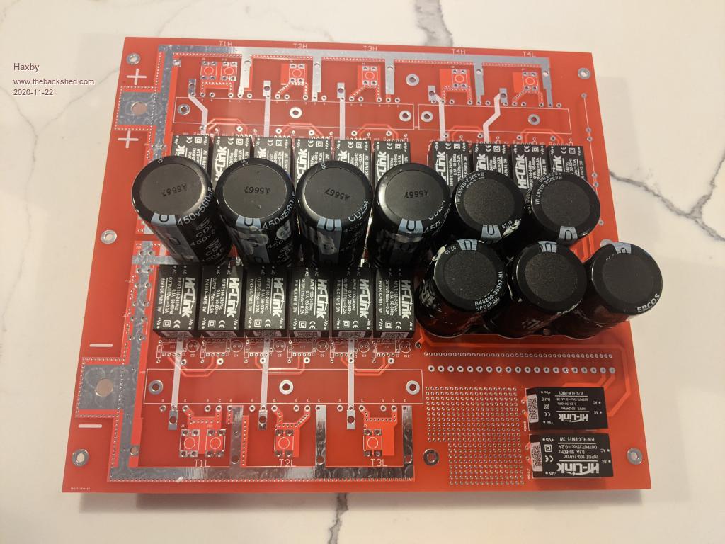 Just waiting on the heat sinks to arrive so that I can finish it off and start testing. Transformers are all good to go. I'll solder 5mm diameter copper rod to the exposed tracks to fortify the current handling. |
||||||
The basic design criteria that I follow is to design all four transformers to work with an assumed sinusoidal primary rms voltage equal to the minimum dc voltage the inverter will ever see. And at 50Hz and with a flux density of around 1.0 Tesla. So if you take an off the shelf commercial transformer designed to work from the usual 230v rms grid voltage, that would work in a warpverter designed to operate between 230v dc input and 460v dc input. This works, because at the minimum dc input voltage (230v) the transformer duty cycle will be at its longest, the on time will be relatively long, the off time relatively short. That sets the basic design flux swing in the core. If we were to increase the dc input voltage up to 460 volts, and we halved the duty cycle, the on time is only half, and the flux swing in the core remains the same. This happens automatically, as the dc input voltage is increased we keep stepping up to a higher lookup table, and to maintain a constant ac output voltage from the inverter the waveforms of all four inverters become narrower and the duty cycles all decrease. As the inverter provides a near constant output voltage, that is all the transformers need to do. As the dc input voltage increases the primary rectangular wave waveforms, change in shape and duty cycle, but the CURRENT through all four transformers remains an identical sinusoidal shape. So if you wish to operate from 230v dc minimum to 460v dc maximum, you will need four transformers. 230v 50 Hz sine wave primary to 225v secondary. 230v to 75v secondary. 230v to 25v secondary 230v to 8.33v secondary. And yes you can use off the shelf transformers without any further calculations. The only thing to be aware of though is that commercial transformers are almost always designed for a higher flux density, typically 1.6 Teslas. They do that to use less iron and fewer turns (less copper). It makes for a smaller lower cost transformer. For us, the down side of running a higher design flux density would be a fairly significant increase in inverter idling power. A second disadvantage can be a very high initial current surge at power up. You can test your proposed transformers on grid power. If idling power is high, and there is a big switch on surge, its going to do the same thing in your inverter. |
||||||
Thanks warpspeed. Looking forward to trying it out! |
||||||
The heatsinks came in today so I'll be mounting the IGBTs. The heatsinks were pre-drilled and tapped by the manufacturer, which is nice and convenient. 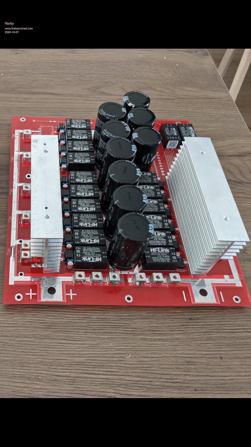 Edited 2020-12-07 13:40 by Haxby |
||||||
Golly that looks really nice, better than a bought one ! I suggest you start off with just four IGBTs in the largest inverter and see how that goes first. Expect to see some massive voltage overshoot across the transformer secondary. Don't worry, the waveforms will all look pretty rough and crappy right up until you connect up the fourth and smallest inverter, and get that finally running. At that point of completion, the currents through all eight transformer windings will be purely sinusoidal and magic happens. One thing is for sure, these transformers hate square wave currents, and that massively distorts the voltage waveforms in the secondaries. And that is what you will be looking at until all four inverters are working in complete harmony. The whole thing is a bit unusual in the way it works. And I think you are going to be really surprised the effect adding the fourth "tiny" inverter has. |
||||||
Good news: the high voltage warpverter is nearing completion. Here is a pic of it running on 3 inverters. A big thankyou to warpspeed for all the input to get it to this stage. It has been a great covid lockdown project. I blew up some IGBTs doing something silly so the 4th inverter will have to wait for another day. There are some unidentified spikes on the oscilloscope. Not sure if I trust the oscilloscope though. It's a cheap $40 oscilloscope connected through a 200k voltage divider. For those not following the thread, the toroids are all unmodified, save for a few extra windings to get the volts right. The two biggest toroids are a 3kw aerosharp and a 1.5kw aerosharp. I'm hoping to use this on my 200v DC Prius battery, but it should work unmodified up to 400v. Load testing to follow. And in case you are wondering, that 5th toroid is the isolated mains input power supply. I wasn't game enough to try it right off rectified mains for the first tests. 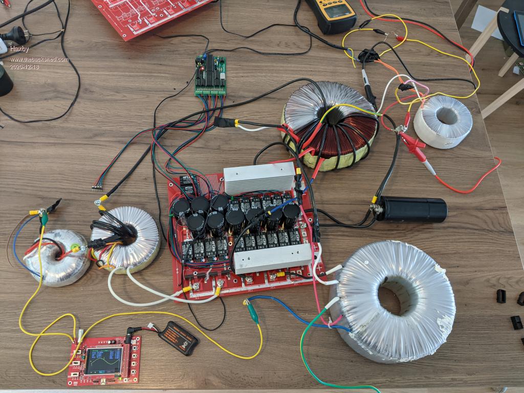 |
||||||
I have one of those "Barby Doll" small oscilloscope boards, and it did exactly the same thing. Random spikes that blink on and off. I would not worry about it, they are almost certainly not really there. I fixed mine with a simple low pass R/C filter ahead of the oscilloscope. Looking at the mains waveform with a real oscilloscope, it looks clean. You will find the smallest inverter makes a big difference. Well done !! Excellent progress. |
||||||
Disaster strikes: After mounting everything in some 19" rack enclosures, and running from a low current 140v dc supply, I was then game enough to try it on rectified mains. Standing back, I plugged it in..... I measured the output voltage as 160v, which was surprisingly low. But a nice sine wave appeared, so I thought it just needs a tweak on the multiturn pot. Not remembering what voltage divider resistors I used on the warpverter, I took the board out, and had a look. I used a 200k on the top and 3.3k on the bottom .... Seems reasonable for a 330v DC input voltage? So not sure why the output voltage was so low... I plugged it in again, and bang, blown IGBTs on the second largest inverter. Looking at the warpverter board, I noticed that I had somehow bumped the icl7860 IC and one side of the package was no longer plugged in... The -5v rail would have been disconnected. Would losing the -5v rail have caused the IGBTs to short out or should I look elsewhere? |
||||||
I have no idea really, but the ICL7860 just determines which of the 256 different lookup tables is selected. Now if you select the lowest lookup table (00) and feed in a relatively high dc voltage into the inverter, that may very well saturate one of the transformers, and create some very high current spikes in the IGBTs. Think about what happens if you plug in an ordinary 230v rated transformer to 330v ac or 460v ac !! The Warpverter selects a suitable lookup table (and drive waveforms) to create a 235v sine wave output. If a totally unsuitable lookup table is selected, either the output voltage may be very low, or it might easily drive the transformers into saturation attempting to generate some freakishly high output voltage. I have never observed that effect myself, but its theoretically possible. Once the primary saturates only the ohmic resistance of the winding limits the current, which can be destructively high. This is all speculative. But be very sure that any CMOS chip is well socketed, and has no floating inputs, and be doubly aware of electrostatic discharge damage. Edited 2021-01-09 15:33 by Warpspeed |
||||||
More popped igbts today I'm sorry to report!   . . I replaced the IGBTs on the second largest inverter, and checked all the MOSFET driver ICs. I found a bad hi-link power supply too. Before connecting the transformers I powered up and took readings on the outputs. The second largest inverter output (with no transformer connected)shows this trace. Could it be the dead time capacitors? I'm using 10nF caps across the opto driver:  After replacing and checking components, I powered up with 330vdc, this time with a 1000w halogen bulb in series with the power supply to limit the current. The bulb lit briefly as the caps charged, then extinguished, then lit up again a second later as the inverter IGBTs shorted out. |
||||||

