|
| Windmill Kit, no longer supplied.. |
|
Stator Rewiring
 From
factory the Fisher & Paykel stator is wired into one large
star winding, producing 3 phase AC when used as a generator*.
If we were to use this on our windmill the output voltage
would range from 0 to 300 volts unloaded, and up to 2-3 amps
maximum loaded, not a very usable range for charging batteries. From
factory the Fisher & Paykel stator is wired into one large
star winding, producing 3 phase AC when used as a generator*.
If we were to use this on our windmill the output voltage
would range from 0 to 300 volts unloaded, and up to 2-3 amps
maximum loaded, not a very usable range for charging batteries.
So we are going to rewire
the stator into 7 little windings all in parallel. This will
give us an output range of 0 to 40 volts unloaded, and over
20 amps loaded, a little more practical for our purpose.
* Technically its
an ALTERNATOR, but the term GENERATOR is more commonly used.
But before we start, I need to talk about
"cogging". Cogging is the term we use to describe
the effect of the hub magnets attracting the stator poles,
making it difficult to rotate the hub from a standstill. It
takes more force to start the rotation, than it takes to keep
the rotation going. Imagine an old car and a series of small
hills and valleys. From the bottom of the first valley, its
very difficult to get up the first hill, and if the car hasn't
got enough power it will end up going backwards back down
into the valley. But once the car gets over the first hill,
it has enough momentum to get over the next hill, and the
one after that, etc.
How does this affect our windmill. Well from
standstill a windmill has very little power, the blades are
not designed to work that way, so in light winds the windmill
may not have enough power to get past the first cog. This
means the windmill wont start, even though there is enough
wind to make usable power. We call this "cogging".
| There are a few ways to get past this
problem. We can use bigger blades with more power, at
the cost of high speed performance. We can "decog"
out stator by rounding off the stator poles and reducing
the magnetic"edge". Rounding of the stator poles
is best done with a power file, you just want to remove
the sharp edge of the stator laminations. For more information
on de-cogging, visit the excellent EcoInnovation web site,
the the Smart Drive information sheets. http://www.ecoinnovation.co.nz/links.php?code=8 |
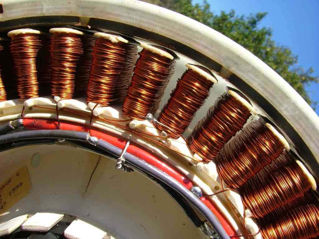
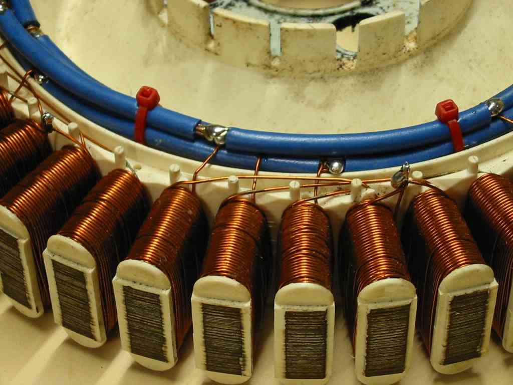
 Close up shows
the de-cogged stator, click to see full size.
Close up shows
the de-cogged stator, click to see full size. |
Another way is to convert the motor into a
7 phase alternator. In factory form its a 3 phase alternator,
but with a magnet hub from a different model F&P washing
machine, we can run the alternator as a 7 phase, imagine 7
small hills instead of 3 big hills for our car to get over.
The 7 phase conversion works very well, with virtually no
cogging, but its a different re-wire process than that shown
on this page. If you want to try a 7 phase conversion, follow
this link articles/coglessFP.asp
OK, Back to our 3 phase conversion.
| At right is
a diagram of the stator factory winding. I've labeled
the phases X Y & Z. Remember you can click on these
diagrams to see full size. This a 1 group of 14 poles,
so each phase consists of 14 poles. |
 |
| This is how
we rewire the stator as 7 groups of 2 poles star configuration,
and is the easiest and most common way to modify the stator. |
 |
| And this is
how we can wire the stator to use for either star or delta
configurations. Anyone who read the Silicon Chip articles
I wrote will be familar with this layout. The star/delta
option gives you the ability to connect the stator as
a star or delta. Delta will produce more power at high
revs, but star will start making power at lower rev's
and is the prefered option. |
 |
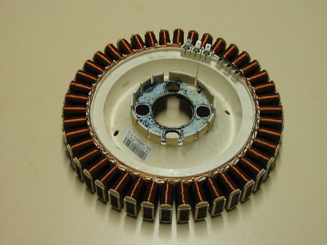
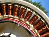
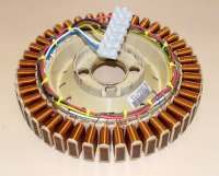
| The standard
stator. First remove traces of corrosion and file off
any rust on the laminations |
|
| Cut the winding
at every 6 poles. This will give you a total of 7 groups
of windings, each with 6 poles, 2 poles per phase. Remember
you can click on these photos for a closer look. |
|
| With sandpaper,
clean the enamel off all leads for approx 15mm from ends. |
|
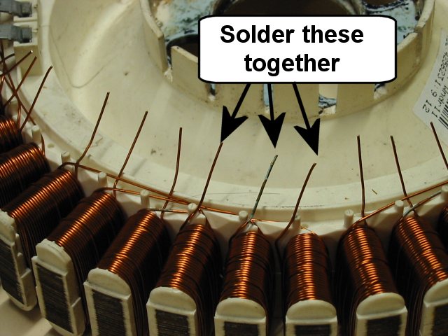
| If you are making
a 3 wire star stator, twist and solder the star mid point
connections. |
|
| Strip lengths
of wire as shown. Use wire capable of at least 15amps. |
 |
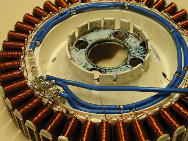
| Solder three
( or six if you are going for the 6 wire star/delta option
) lengths of heavy electrical cable ( 4-5mm dia copper
) to the original connection terminal terminals, then
strip back 5mm at each connection point. Cut the cables
at the last connection point. This will form our power
"bus". Wrap each star end wire around the bus
wires as shown, and solder. You will need a good soldering
iron for this. |
|
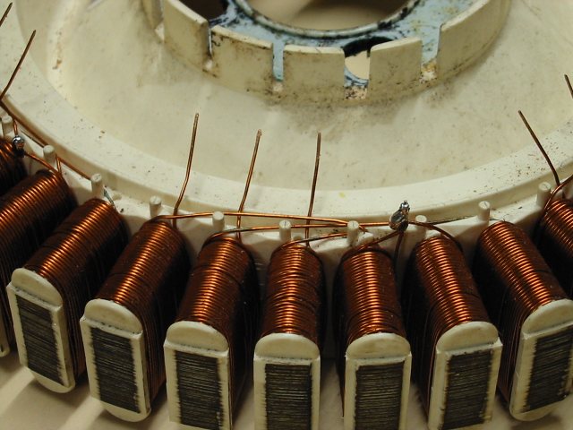
| Once all star
windings have been soldered, cable tie the bus wires to
secure the assembly. |
|
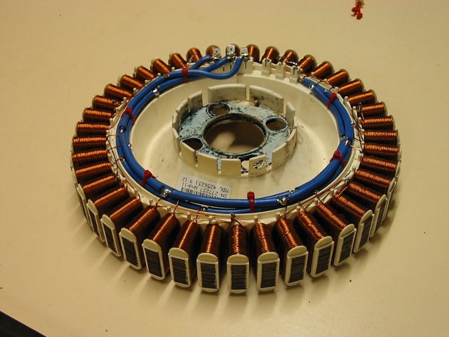
| The finished
stator. Give the stator a good coating of varnish ( or
similar ) to protect from the weather. |
|
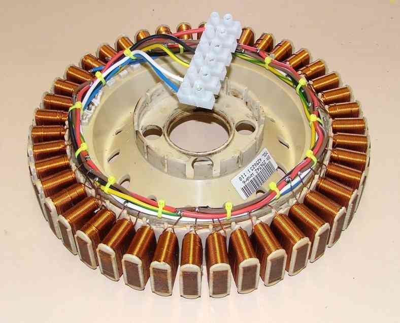
| If you decide
to wire as a 6 wire delta/star configuration, you stator
should look something like this. |
 |
| If you use a
6 wire star/detla configuration, the diagram at right
will show you how to connect the output leads together. |
 |
Next
- Bearing Plate Assembly
|