 |
|
|
|
Site Navigation
Projects & Information
»General Information»Wind turbine Projects »The F&P Smartdrive »Electronic projects »Microcontroller projects »Miscellaneous Kits & Parts
»Basicly Natural Pty Ltd»PVC & Aluminium blades »Scale model farm windmills »Price Watch Discussion Forums
Handy Links
»Wind»Solar »Electric Vehicles »Electronics »Micro Controllers »General Interrest About TheBackShed Getting Started Privacy Policy |
There has been a lot of interest in using capacitors to improve the output of the F&P Smartdrive based windmills. The capacitors make up for any in-efficiencies in the F&P's iron core design, give a marked improvement in the windmills output, and the same techniques could be applied to any alternator. This is not a subject for the beginner. Using capacitors to improve a windmills performace will require some experimentation and analysing of test results by the builder to get the best results. There are also some safety issues that need to be taken in account, if you dont know what you are doing you could be a victum of electrocution or capacitor explosion. Put simply, dont use caps on your first windmill. Early experiments had the capacitors connected in parallel with the Smartdrive output, as shown below.
This configuration gave an improvement, but it wasn't until someone tried the capacitors in series with the Smartdrive outputs that the real possibilities of using caps to increase power started to emerge.
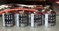
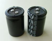
The Capacitors As the capacitors will be used in a AC circuit, non-polarised AC caps need to be used. Originally motor caps were tested, but these are usually only a few uF in value and expensive, a cheaper option is to use DC electrolytic caps back to back, as shown below. Its OK to connect DC caps back to back like this so long as they are overated, eg a 400VDC capacitors are used in a 24v circuit. When connecting the capacitors in series, the uF value is halved, so if you want a 100uF AC cap, you would need to use 2 200uF caps back to back.
Please note, the capacitors in these circuits can store a lethal charge. If the windmill is run without a load, even if just for a few seconds, the capacitors will charge to several hundred volts. Even if the windmill has stoped, the capacitor charge will remain and must be considered lethal. In all circuits I've added a bleed resistor ( R* ) across the rectifier outputs. This should be a 10k 5 watt resistor. A better option is to add a 100k 1watt resistor across each back to back capacitor pair, as shown below.
When performing any maintenance on a capacitor modified alternator, please remember to test for any stored voltage with a multimeter before touching any connectors. Even with the bleed resistors, it would be worth while using a 47ohm resistors and shorting clips across the capacitors, just to be sure. Thanks to Phill and Ross for the safety tips. One of our forum members Gordon has done a lot of research and testing of using caps on the F&P, so I'll hand it over to him......... The use of capacitors in the arrangements that follow is directed towards load matching of a WINDMILL alternator and not power factor correction. There are basically 2 types of arrangements, both requiring AC rated capacitors, or DC types wired as equivalent.
|
||
|
2. is the arrangement I have developed. This uses combinations of capacitor voltage multipliers, in a 3 phase parallel arrangement. The simplest form is a capacitor voltage doubler in parallel with std rectifiers to the battery load, as in this circuit. [ This circuit would suit a alternator that has a high cut in speed, compared to the circuit above that suits alternators with a low cut in speed. For example a Smartdrive reconfigured as a 2 pole SP would cut in at a much higher RPM than a standard stator. This circuits uses a voltage doubler to harness the low RPM power that would normally be lost. The circuit below uses the common 35Amp bridge rectifier instead of individual diodes ]
The capacitor voltage multipliers are placed in parallel with the main rectifiers, and there can be doublers and triplers and quadruplers etc. The capacitor sizing for each type is different, even though the voltage rating would be the same. A quadrupler would have smaller caps than a tripler, and these would be smaller than a doubler. The power handled by each arrangement is different. The caps effectively convert the abrupt loading charastic of a windmill connected to a battery, into one that the alternator is loaded in a manner that is proportional to the wind energy that is passing. The rotor speeds up and down proportional to the windspeed and the changing characteristics of the capacitors with windmill AC frequency and the combination of ccts, gives a varying loading with a close to cubic power relationship to doubling of windspeed. The choice of capacitor size determines how close to optimum the loading is. The loading should be slightly underloaded so the blades TSR continues to stay just slightly above the optimum. This ensures a smooth response of the loading to the changing windspeed. The calculation of capacitor sizing continues to be the most difficult task. I size the various arrangements this way.
In the arrangement I have on my Dual rotor AxFx windmill. I have a voltage quadrupler, a voltage doubler, and series caps. I do not have a direct rectifier on the windmill to the battery. My system is 48V nom battery, and the capacitors on the quadrupler are 200VDC back to back 220uF, with 10A 200V bridge rctifiers. The caps on the doubler are 350VDC back to back 560uF, with 35A bridge rectifiers. There are 2 sets of series caps. One set is 350VDC back to back 820uF with 35A rectifiers, and there is a second parallel set of 180VDC back to back 1500uF with 35A bridge rectifiers. As it turns out, all the caps need only be 200V rated. My windmill is rated 1500W. The reason I have series caps, is that my windmill is stalled when connected directly to the 48V battery. In my arangement, the quadrupler passes approx 1A at full power, the doubler passes approx 5A, and the series caps pass 25A. My rule of thumb is for a windmill of the same power rating, that for a halving of the system voltage, the capacitance is doubled. The capacitance is proportional to the power rating of the windmill. The power handling of the capacitors determins the physical size required. The voltage usually determins the physical size of the same capacitance value. Lower system voltage does not dictate lower voltage caps. I would not use caps rated at lower than 180VDC in a back to back arrangement. 12V systems suitability is often asked. I have no data, but it should still work, but with a higher proportion of diode loss. The best system is one where the alternator is wound for a normal battery cutin rpm of approx half the intended maximum rotor rpm. This allows normal rectifiers and a cap voltage doubler, and quadrupler. This reduces the effective cutin to approx 1/4. In this example, say the alternator was expected to have a 500rpm max rpm. The normal cutin would be approx 250-300rpm, so the alternator would be wound for this. The voltage quadrupler would bring cutin down to 60-70rpm. The output power would increase up to 120-140rpm, where the voltage doubler would start to contribute. As the rpm increased up to 250-300rpm, the power output would still be increasing, until the normal rectifiers started to pass current as well. All the time, each of the cap cct is adding its additional increasing power contribution. The capacitance sizing determins the best cubic power fit. Normally, the blades will operate across a wide windspeed range with similar efficiency within a tight optimum TSR. The range of windspeeds that the windmill can be expected to produce battery charging current is increased by a factor of at least 3. The alternator loading can be relatively easily tuned to the rotor externally. The electrical solution replaces an electronic windmill MPPT system with only capacitors and diodes. Gordon ( GWatPE ) To find out more about the cap mod, see the following thread in our forum.... http://www.thebackshed.com/Windmill/FORUM1/forum_posts.asp?TID=1138&PN=2&TPN=1 http://www.thebackshed.com/Windmill/FORUM1/forum_posts.asp?TID=1424&KW=testing
Sourcing the capacitors. It's highly recommended new capacitors are used for Gordons cap mod. Used capacitors from PC power supplies are usually not equal in value and will fail very quickly. The caps are available from the following suppliers, keen an eye out for specials/sales, and its also worth looking on e-bay.
|
|||
 Do not mount a resistor across each individual capacitor, nothing must be allowed to touch the intermediate terminal between back to back caps. A resistor connected to the intermediate terminal will destroy the assymetric leakage current, which protects the oxide layer within the capacitor. A bleed resistor across a back to back pair will result in no potential left across the pair ( it will bleed off to zero), but full potential will remain across one of the capacitors until the capacitors own internal leakage bleeds it away. Therefore some physical mechanism needs to be in place to make it impossible to touch the middle terminal as it will be alive, but as a unit it will be benign with a normal bleeder as would any AC capacitor with a bleeder resistor. They must be treated as a unit only, not individual caps.