
|
|
Forum Index : Microcontroller and PC projects : Thinking about a new Pico PCB design for integrating into a keyboard
| Author | Message | ||||
| Mixtel90 Guru Joined: 05/10/2019 Location: United KingdomPosts: 5725 |
Probably the cost - looks like it might be a slightly modified standard board. Maybe not even modified. It only needs to run small Android apps anyway. Mick Zilog Inside! nascom.info for Nascom & Gemini Preliminary MMBasic docs & my PCB designs |
||||
| Pluto Guru Joined: 09/06/2017 Location: FinlandPosts: 329 |
I am impressed by the nice PCB designs that you are developing. Looks very professional! Esthetic design is not my strenght.... This is my latest version of PicoMiteVGA. Quick and dirty, but quite handy despite the quite heavy keybord from an old COMPAQ. (Still plenty of room for future add-ons). I thought it was better to have the grandchildren (3 and 5 years) hammering in readable and non-readable text on this thing than using my laptops or desktops. Furthermore I think they need to get gradually used to MicroMite Basic  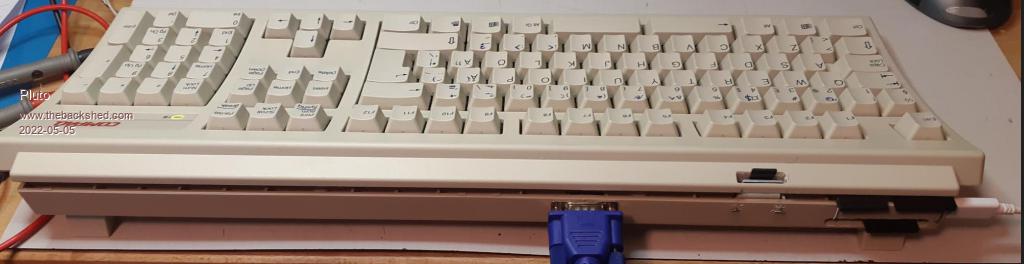 PicoMite to the right, VGA connector in the center and SD-card in between. RTC inside. Female connectors on the available ports directly soldered on the Pico module. Circuits for keyboard and VGA built on prototyping PCB. All according to the guidelines in the manual. Works perfectly.  Unfortunately the Swedish/Nordic keyboard is not yet supported by the PicoMiteVGA firmware. Some keys are now pen-labeled with corrected characters.  I hope that our keybords will also be supported some day. I hope that our keybords will also be supported some day. /Fred |
||||
| lizby Guru Joined: 17/05/2016 Location: United StatesPosts: 3015 |
Nice looking. Congratulations. In this post , matherp said Swedish keyboard for MMBasic for Windows was supported. Maybe if you can confirm that your keyboard works in MMB4W, then support for that keyboard might be added to the Picomite. PicoMite, Armmite F4, SensorKits, MMBasic Hardware, Games, etc. on fruitoftheshed |
||||
| gob33 Newbie Joined: 26/02/2018 Location: FrancePosts: 6 |
Something that is reproductible for every one: a wood based keyboard case. Easy to drill. Heavy and nice. Example: KL90 from Barrett Creative - An artisan making little series. Other possibility: Alu keyboard case. Edited 2022-05-05 09:30 by gob33 |
||||
| phil99 Guru Joined: 11/02/2018 Location: AustraliaPosts: 1781 |
Pluto's setup is similar to what I have done, no PCB. Instead of trying to cram a PCB into the keyboard there may be more room for it in the monitor. Free 5V power too. Some also have an audio amp and speakers. |
||||
| Pluto Guru Joined: 09/06/2017 Location: FinlandPosts: 329 |
Peter M has successfully implemented Swedish (SW) keyboard in MMB4W, but as far as I have tested and tried it is not yet available in PicoMiteVGA. Btw: For the keyboard levelshifters I have used Si2302 N-channel mosfets. SOT-23 soldered to tiny adapters before attaching to the prototype PCB. As i found these working on my first proto, i did not bother to test anything else. (>90pcs still on my stock, $3.30/100pcs). |
||||
| Volhout Guru Joined: 05/03/2018 Location: NetherlandsPosts: 3521 |
Mick, Got my components today (1.5mH, 8.2nF) and the filter works. But I am not 100% happy. It will be fine for the average computer sound, but for hifi there is a snag. When you generate 1kHz via 44kHz pwm, you get 1kHz, but also 44-1=43kHz spurious. The lc filer will reject the 43kHz But when you generate 20kHz, you get spurious 24kHz. And that is not rejected. Similar 10kHz will have 34kHz spurious. Some of it is rejected, but not all. So not good enough for hifi, but sufficient good for average game sounds. I will put the filter in my VGA mite (peters board) The pico IO pins have 50 ohm internal resistance. Not very good for this circuit driving a low impedance headset, but it works. Also tried the active filter with opamp lm358, works but has problems driving the headphone 32 ohm. It is clipping. Maybe with a different rail to rail opamp is works okay. Edited 2022-05-06 07:12 by Volhout PicomiteVGA PETSCII ROBOTS |
||||
| Mixtel90 Guru Joined: 05/10/2019 Location: United KingdomPosts: 5725 |
I did wonder if there might be harmonic problems - I didn't consider the sproggies. Is it worth considering reducing the Q factor (resistor across the inductor?) and widen the notch a bit? Not that many people will be bothered about reaching 20kHz - this isn't a hi-fi box, although some may use it to listen to music on computer speakers. If it gets to 16-18kHz it's probably enough. I've been re-hashing the PCB. I've laid out the audio end, incorporating 2-series clipping diodes across the first cap to ground. Managed to get all the caps as polybox types lying flat (I doubt if there will be anything bigger used) and 6.5x3mm axial inductors. The video signal traces have been shortened a bit and there is space to put series resistors on the sync lines now (or just wire links). I've just managed to get rid of the level shifter too, and put mosfets by the PS/2 socket. Still tweaking. :) Mick Zilog Inside! nascom.info for Nascom & Gemini Preliminary MMBasic docs & my PCB designs |
||||
| Volhout Guru Joined: 05/03/2018 Location: NetherlandsPosts: 3521 |
Mick, to be honest, the picomite itself is the culprit. It's limitted IO current does not make it easier. You want to hear audio in a 32 ohm headset, which leads to some 300 ohm max series resistance. The io pin is 50 ohm already. I measured that with 220 ohm load you already loose 20% if its amplitude. To make a filter you design around 200 ohm input and output impedance. To lower the Q of the filter would require a larger inductor. The 1.5mH I use already have 30ohm. A 3.3mH similar size would have 50-100 ohm. This results in reduced 44kHz suppression. The whole filter is a balancing act between fewer components, performance, and easy assembly. I have implemented the LC filter to run it through its paces, but if I design a board myself, I would put the active filter on it. And try to find a rail to rail opamp that can drive a headset. The LM358 clearly cant. And I would probably use 1206 size SMT, since that is not difficult to assemble. The active filter amplfier has more components, but in SMT is smaller size. Edited 2022-05-06 18:46 by Volhout PicomiteVGA PETSCII ROBOTS |
||||
| Mixtel90 Guru Joined: 05/10/2019 Location: United KingdomPosts: 5725 |
That's fine - I'll go with the passive system in this instance anyway. I want to keep it easy to assemble, even for those who don't like surface mount. The headphones are a "nice to have" option, I suspect that quite a few will use amplified speakers. If I was putting this anywhere else other than underneath a keyboard then things might be different. :) The loss of output to the phones isn't really a problem. I've tried 680R series resistance and it's been acceptable. Ok, the quality isn't great, but it works. Someone will plug 8R phones in at some point and discover the real problem. lol �I even tried 1k, but it's getting a bit quiet and nasty by that point. You need about 220R minimum resistance anyway as protection for the Pico output into a shorted jack socket. You can't rely on turning down the volume in software in this case. It works to a point, but it's better quality to keep it as close to max as possible. That means that there have to be losses in the filter network at some point as the volume is simply too loud. You can turn game sounds and music down no problem, but not music that you might actually be listening to. Edited 2022-05-06 19:11 by Mixtel90 Mick Zilog Inside! nascom.info for Nascom & Gemini Preliminary MMBasic docs & my PCB designs |
||||
| gob33 Newbie Joined: 26/02/2018 Location: FrancePosts: 6 |
Andrew Mathieu did its own adaptation of Lee "Legion" Smith 3D printed case. Files on Thingiverse 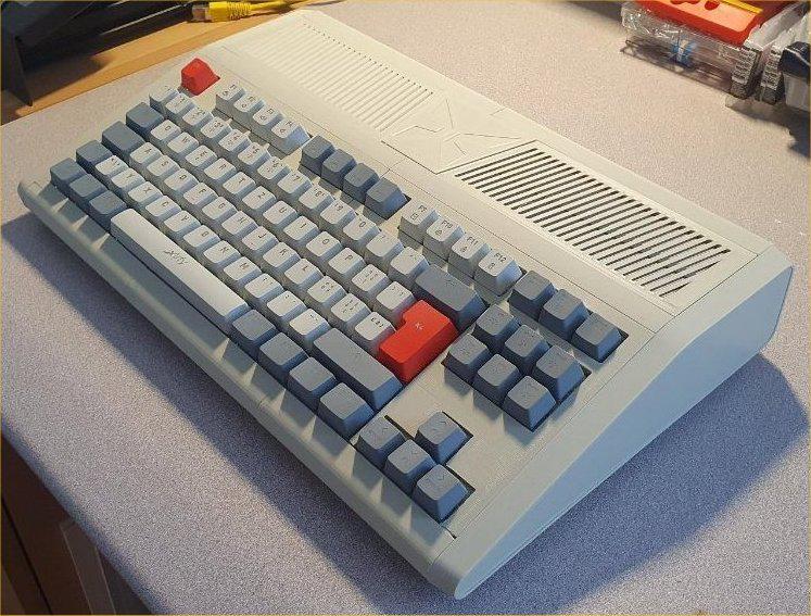 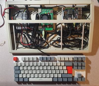 |
||||
| Mixtel90 Guru Joined: 05/10/2019 Location: United KingdomPosts: 5725 |
That's rather nice. :) Mick Zilog Inside! nascom.info for Nascom & Gemini Preliminary MMBasic docs & my PCB designs |
||||
| Mixtel90 Guru Joined: 05/10/2019 Location: United KingdomPosts: 5725 |
This is where I'm up to at present. picomite keyboard 2.zip I've measured a fairly slimline keyboard, which is just short of 140mm front to back. The fold-down feet at the back lift it about 13mm. With a little care this board should fit neatly under this and any other similar-size keyboards (mechanical or otherwise - you just need a gap), projecting about 19mm from the back, to the rear face of the VGA socket. It fits when I draw it on CAD anyway. :) I've incorporated the audio filter that I've been discussing with Volhout, but also included the series diodes to clip the PWM output. Not certain if these are still required? They give some protection to the PWM pins anyway. Of course, there's no reason why this design should only be used for a keyboard. It could be used anywhere where a VGA system is required and all the connections are required on one side. The PCB is 125mm x 55mm. Mick Zilog Inside! nascom.info for Nascom & Gemini Preliminary MMBasic docs & my PCB designs |
||||
