
|
|
Forum Index : Electronics : driving via canbus Eltek 2kW Flatpack2 supplies
| Page 1 of 5 |
|||||
| Author | Message | ||||
| poida Guru Joined: 02/02/2017 Location: AustraliaPosts: 1481 |
Another project that I need to get going is to develop some custom code and hardware to control a number of Eltek power supplies. Wiseguy and I have been looking at a problem he has. Commercial products are available that can and do control these supplies via canbus. But our needs are special so it means do it yourself. Step 1 get some SPI to canbus transceiver boards. Connect one to an Arduino Uno. Note well that canbus transceiver earth/ground needs to be tied to Eltek supply DC output ground step 2 observe data flows. I am stuck at step 2 Here is what is on canbus High and low wires. This is output even if the canbus transceiver is unpowered. I have 200R termination present and when absent there are spikes in the hi/low or low/hi transitions as well as rounded risetime. So the termination resistors stay. 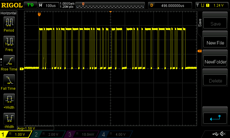 it is 125KHz canbus speed. 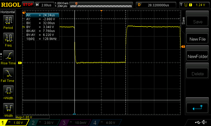 and the supply spits this particlar data stream out continuously Here is the signal. No idea what it means. 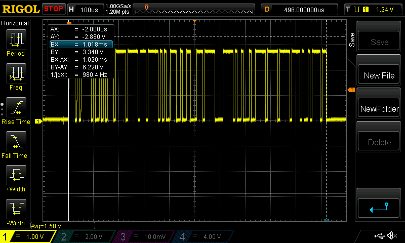 Anybody here know much about canbus? Is this signal suitable for input into the MCP2515 canbus transceiver chip to be detected correctly and converted to data? wronger than a phone book full of wrong phone numbers |
||||
| SimpleSafeName Guru Joined: 28/07/2019 Location: United StatesPosts: 351 |
Which Rigol do you have? Some of them with "field upgrade" (google your model) can interpret Canbus directly. https://www.youtube.com/watch?v=METmiiieV6Y |
||||
| poida Guru Joined: 02/02/2017 Location: AustraliaPosts: 1481 |
I have the DS1054Z with all options enabled here at home. At work I have a DS2072 with all options. But decoding canbus is no longer needed. I have some code working now that can talk to and listen from the Eltek. I just changed the default output voltage to 48.00V Now to change default current limits... #include <SPI.h> #include "mcp_can.h" #include <mcp_can_dfs.h> unsigned char login[8] = {0x16, 0x36, 0x71, 0x07, 0x03, 0x76, 0x00, 0x00}; //this is for logging into your flatpack. Must use your serial number. const int SPI_CS_PIN = 10; MCP_CAN CAN(SPI_CS_PIN); // Set CS pin #define VOLTAGE 4800 #define CURRENT 0100 uint8_t outset[8] = {CURRENT & 0xff, (CURRENT >> 8) & 0xff, VOLTAGE & 0xFF, (VOLTAGE >> 8) & 0xFF ,VOLTAGE & 0xFF, (VOLTAGE >> 8) & 0xFF ,0x3E, 0x17}; void setup() { Serial.begin(115200); pinMode(3,INPUT); START_INIT: if(CAN_OK == CAN.begin(MCP_ANY, CAN_125KBPS, MCP_8MHZ)) { Serial.println("CAN BUS Shield init ok!"); } else { Serial.println("CAN BUS Shield init fail"); Serial.println("Init CAN BUS Shield again"); delay(100); goto START_INIT; } CAN.setMode(0); delay(200); CAN.sendMsgBuf(0x05004804, 1, 8, login); // id = 1 so XX = 04 } void loop() { unsigned char len = 0; unsigned char buf[8] ; int c=0; if(CAN_MSGAVAIL == CAN.checkReceive()) { CAN.readMsgBuf(&len, buf); uint32_t canId = CAN.getCanId(); Serial.print("0"); Serial.print(canId,HEX); Serial.print("\t"); for(int i = 0; i<len; i++) { if( buf[i] < 0x10){ Serial.print("0");} Serial.print(buf[i],HEX); Serial.print(" "); } Serial.println(); Serial.print("Temperature = "); Serial.println(buf[0]); Serial.print("Current = "); Serial.println(buf[2]*255*0.1+buf[1]*0.1); Serial.print("OutputVoltage = "); Serial.println(buf[4]*255*0.01+buf[3]*0.01); Serial.print("OutputPower = "); Serial.println((buf[4]*255*0.01+buf[3]*0.01)*(buf[2]*255*0.1+buf[1]*0.1)); Serial.print("InputVoltage = "); Serial.println(buf[5]); //send request for new update CAN.sendMsgBuf(0x05004804, 1, 8, login); // XX = 04 //CAN.sendMsgBuf(0x05FF4004, 1, 8, outset); } } and I get (etc.) 05014004 20 0F 00 C1 12 F3 00 2D Temperature = 32 Current = 1.50 OutputVoltage = 47.83 OutputPower = 71.74 InputVoltage = 243 (etc.) in the serial terminal. I can talk to it! wronger than a phone book full of wrong phone numbers |
||||
| wiseguy Guru Joined: 21/06/2018 Location: AustraliaPosts: 1297 |
Well done Poida ! I surmise that the allowable adjustment for the Elteks is in the (from Memory) 43-54V. I also seem to recall that for a constant current each communication to the Eltek requires the current information to be sent, however (again this is second hand) for voltage once the value is sent it stays that way when polled until another updated value is sent. Still reading the forum when I have time, we are finally shifting house to the new address on Tuesday. If at first you dont succeed, I suggest you avoid sky diving.... Cheers Mike |
||||
| wiseguy Guru Joined: 21/06/2018 Location: AustraliaPosts: 1297 |
I shall recap on my initial (ambit) requirements for the controller. A display of the Eltek(s) output current and voltage. Perhaps the Set Current (I Limit) and Set Voltage, visible when supply is not enabled. If there are 2 or more Elteks, on power up the software should sniff the comms line ie ping address range and note any replies received. If there is more than 1 Eltek, assume the outputs are in parallel. It would be nice if the controller would add the Elteks currents together and display the sum total. If the current limit is set to say 60A then the controller would divide that by the number of Elteks and set them each to 20A ( ie 3 x 20A = 60A ) I will leave a possible display and how to set values open for the moment to see what suggestions come up as cost effective and not too arduous to program. I guess if it all gets too hard a 16 x 2 could do the job. One button for Enable/Off, one button for Amp/Volt and 2 buttons for Up/Down control. We probably need a way to set their initial address to ie "1", "2", etc This spec is shooting from the hip - I may have overlooked some basics..... If at first you dont succeed, I suggest you avoid sky diving.... Cheers Mike |
||||
| poida Guru Joined: 02/02/2017 Location: AustraliaPosts: 1481 |
The flatpack2 48V 2KW has a output voltage range of 43.5 to 57.6V I suspect if I command it to go outside this range it will ignore me. Max current is 41.7A at 48V which is 2001 W I have not been able to set a current limit and see the unit hit the limit and not exceed it. But I can set any voltage and the unit alters output to the new setting. (assuming it's within the limits..) wronger than a phone book full of wrong phone numbers |
||||
| SimpleSafeName Guru Joined: 28/07/2019 Location: United StatesPosts: 351 |
That's what I have, it is effectively a 1104Z with the upgrade. https://www.instructables.com/id/How-to-Hack-Upgrade-a-Rigol-DS1054Z-Digital-Oscill/ Excellent! Edited 2020-03-30 00:19 by SimpleSafeName |
||||
| poida Guru Joined: 02/02/2017 Location: AustraliaPosts: 1481 |
It's been a while since I worked on this project. I blew 2 canbus to SPI modules, the only 2 I had ($10 each or something.) So I got on to something else that needed doing.(the charge controller) I now have 7 new canbus to SPI modules and it's time to play again. Here is the background info: We can get Eltek 2kW HE power supplies for about $70-80 here in AUS They are very efficient and have near 1.0 power factor. Input is 240V AC, output 43.5 V to 57.4V with an internal 2kW output limit. There are no user controls. All settings are done via canbus. There is some information available on the canbus protocol. Wiseguy has a need to have 2 or 3 of these PS in parallel with control over output voltage & current in total and the individual PS. I was talking with RenewableMark about these things and he wants to use one as a battery charger for his 48V (ex. forklift) battery for the home solar. Today I want to show progress in establishing a basic understanding of control via canbus. A power supply can be run in constant voltage mode (CV) or constant current mode (CC) or both. I have the Eltek working in both modes now. First CV: The Eltek can only output voltage in the range of 43.5 - 57.4V so there is no point directing it to output voltages outside that range. It continues to run, but will never exceed either ends of the limit. I hacked up an Arduino Uno with output voltage control via a potentiometer and it works surprisingly well. Load is a solar buck converter and the 1 Ohm 3kW bucket of water. The code can set the output voltage of course and it can get the Eltek's operating data too, which includes output voltage and output current. I plot the voltage setpoint, output voltage and output current below in Blue, Red and Green. There are 500 data points in this graph and data is plotted at about 5 Hz (5 points a second). This gives you an idea how quickly the PS can respond to changes to the setpoint. Vertical scale is 0,15,30,45,60. Output may exceed 2kW for a second but it is quickly brought back to 2kW by the Eltek's control system. 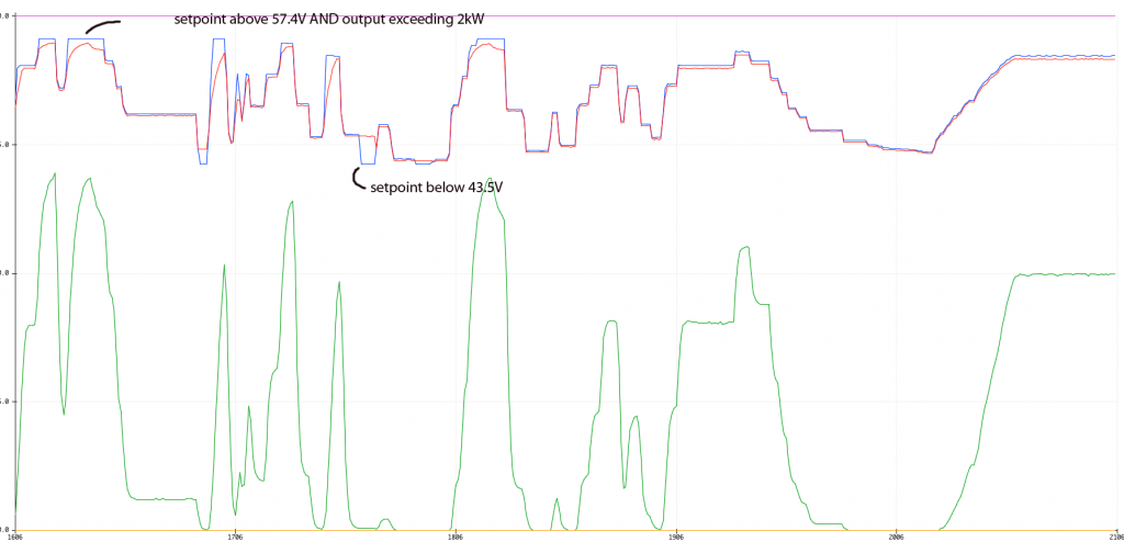 I did some testing to see how the PS operates under CC. Instead of sending a voltage setpoint, I send a current limit to the PS. I had to modify the solar buck converter firmware to simulate a discharged battery. The converter/simulated battery draws maximum power when input voltage is 57V and zero power when input is 45V. This simulates a lead acid battery quite well I think and more importantly this load permits the Eltek control system to reduce the output voltage to bring output current down to the setpoint over the entire range of values (0 Amps to 45A) If I used a resistor I would only have a narrow range of power levels where the Eltek could control output current. The simulated battery load is very non-linear but works as it should. I vary the output current setpoint via a pot and we can see the Eltek track the changes. Blue is CURRENT setpoint, Red is output voltage, Green is output current. It appears the CC tracking is a bit slower than CV. 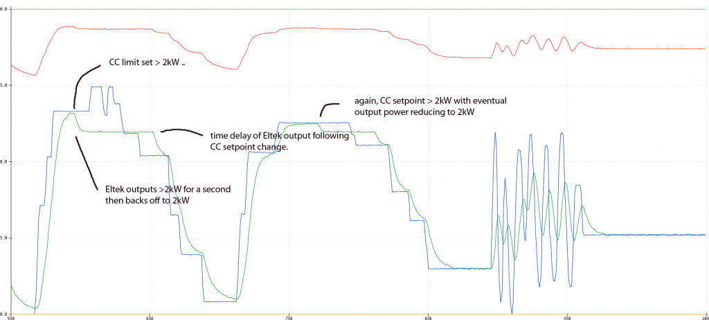 The above results show I can control both the output voltage and current in the manner of a CV/CC power supply which is all we need for both Wiseguy's and RenewableMark's projects. This is simply a proof of concept. The arduino code is nice and robust. It can run at all times, waiting for the Eltek to power up. Once powered, the Eltek then comes under control of the code. I switch off the Eltek and the code is fine, waiting until the next time the Eltek is running. Looking at the battery charger project: The Eltek's 43.5 to 57.4V seems ideal for sealed Lead acid batteries. For flooded cells I would like a bit higher voltage to permit faster equalization. There is a mismatch between the voltage setpoint and the output voltage as reported by the Eltek. At 57.4V output, the difference is about -0.3V with 0.05V noise so the output is 0.3V less than the setpoint commanded by the canbus control. This does not change with output current. At 43.5V it is 0.2V less than the commanded setpoint. This difference might be due to manufacturing tolerances? I think I could make a very nice battery charger using the Eltek and the arduino. I imagine an LCD to show the status of the battery and power supply. We program the absorb and float voltages, maybe maximum current, times to run absorb, maybe a low current limit to automatically switch from absorb to float. The LCD could show charge volts/current/power/amp.hours etc. wronger than a phone book full of wrong phone numbers |
||||
disco4now Guru Joined: 18/12/2014 Location: AustraliaPosts: 1134 |
Following with interest. Have order some bits. Regards Gerry F4 H7FotSF4xGT |
||||
| noneyabussiness Guru Joined: 31/07/2017 Location: AustraliaPosts: 527 |
https://endless-sphere.com/forums/viewtopic.php?f=2&t=67579#p1044262 Ive created a charger from the above info... i also managed to score a proper eltek charge controller, which is yet to be used in anger... scored 9 by fluke for 20 bucks at dump one day ( hen teeth moment), I usually use the modified dc welder for a charger but for 20 bucks !! Also had 4 48v to 24v eltek high current (35 or 40 amp) psu's as well.. I think it works !! |
||||
| wiseguy Guru Joined: 21/06/2018 Location: AustraliaPosts: 1297 |
Thanks for the link noneya a few hours of good reading history with some code examples of the protocol and how they talked to the Elteks with a nano. The most helpful pages for me were 3, 4 & 12 if you want to save a lot of reading. I thought I did good when I bought ten brand new Eltek HE's at $50 each, your "dump" catch was excellent. The Elteks as supplied appear to all be set to a default value of 53.5V. Whilst a controller can be used to set any output voltage within the allowable range, the units can also have their default voltage reprogrammed to a new target such that when powered up with no can controller connected they will now use the new default voltage value ie 44V or 48V as a stand alone. If intending to use the can bus and intending to series two or more Elteks, be aware the can interfaces will need to be galvanically isolated as the can bus for each Eltek are referenced to the negative output terminal. I guess that if the first Eltek unit has a can bus directly connected to it along with the nano, when adding another Eltek/s in series with the existing + terminal of the first Eltek, it means only the can bus that communicates to the "upper" unit/s will need isolation. Peter, the examples noneya linked to may well be examples of how not to write code, but I suspect they might also provide some useful hints and information in the quest to talk to and interpret the information packets flowing back and forth. If at first you dont succeed, I suggest you avoid sky diving.... Cheers Mike |
||||
| poida Guru Joined: 02/02/2017 Location: AustraliaPosts: 1481 |
I read the long post on endless-sphere.com before I started playing with the Eltek. Even though there are working code examples posted there I knew I would not learn much if I just copied it. I had to write my code from the start to force into the thick 'ead the details that sometimes are not apparent from reading code and it's comments. here is the code that runs it in CV mode. I clamp the potentiometer control value to the Eltek output voltage limits before sending it. The control loop executes at about 5 Hz. #include <SPI.h> #include "mcp_can.h" #include <mcp_can_dfs.h> unsigned char login[8] = {0x16, 0x36, 0x71, 0x07, 0x03, 0x76, 0x00, 0x00}; //this is for logging into your flatpack. Must use your serial number. const int SPI_CS_PIN = 10; MCP_CAN CAN(SPI_CS_PIN); #define VOLTAGE 4800 #define CURRENT 450 uint8_t outset[8] = {CURRENT & 0xff, (CURRENT >> 8) & 0xff, VOLTAGE & 0xFF, (VOLTAGE >> 8) & 0xFF ,VOLTAGE & 0xFF, (VOLTAGE >> 8) & 0xFF ,0x3E, 0x17}; volatile int got_cb_data = 0; unsigned char setdefaultvolt[5] = {0x29, 0x15, 0x00, 0x80, 0x16}; float potvolts; void setup() { Serial.begin(115200); pinMode(3,INPUT); pinMode(12,INPUT); START_INIT: if(CAN_OK == CAN.begin(MCP_ANY, CAN_125KBPS, MCP_8MHZ)) { \\ can bus comms OK } else { Serial.println("CAN BUS Shield init fail"); delay(1000); goto START_INIT; } CAN.setMode(0); delay(200); CAN.sendMsgBuf(0x05004804, 1, 8, login); // id = 1 so XX = 04 potvolts = 54.0; } void loop() { unsigned char len = 0; unsigned char buf[8] ; int rv; float a,i,v; unsigned int ui; got_cb_data = 0; rv = CAN.checkReceive(); if(rv == CAN_MSGAVAIL ) { CAN.readMsgBuf(&len, buf); uint32_t canId = CAN.getCanId(); if (canId == 0x05014004 || canId == 0x05014008) { i = buf[2]*255*0.1+buf[1]*0.1; v = buf[4]*255*0.01+buf[3]*0.01; Serial.print (potvolts); Serial.print(" ");Serial.print (v); Serial.print(" ");Serial.print(i);Serial.println(" 0 60 "); } //send request for new update CAN.sendMsgBuf(0x05004804, 1, 8, login); // XX = 04 a = analogRead(0)/660.0; // pot is connected to 3.3V so need this scale for 0 - 1 range. 5V pin is used by canbus adaptor potvolts = 40.0 + 20.0*a; // set demand from 40 to 60V. flatpack has output limits smaller than this range. if (potvolts > 57.4) potvolts = 57.4; if (potvolts < 42.7) potvolts = 42.7; ui = int(potvolts * 100.0); // make changes to control word with new Vout outset[2] = outset[4] = ui & 0xff; // low 8 bits of scaled x 100 voltage outset[3] = outset[5] = (ui >> 8) & 0xff; // high 8 bits CAN.sendMsgBuf(0x05FF4004, 1, 8, outset); } } wronger than a phone book full of wrong phone numbers |
||||
| poida Guru Joined: 02/02/2017 Location: AustraliaPosts: 1481 |
I received another 48/2000 HE, identical to the first one used above. It works fine, needing only one change to the above code, where the 8 byte login string is constructed. I needed to change it to suit the new unit's serial number. Now it's time to look at using 2 units. When in parallel, the 2 units share a common ground, tied to the DC output negative. This is good since I need to communicate via canbus to both and so both canbus to SPI modules will work fine with shared 5V supply, common logic grounds etc. I suspect I will have to use a nano plus the canbus module per unit, and then use another microcontroller to supervise the nanos. I am not sure the Arduino canbus software permits multiple instances. Maybe it does, I need to read a few working examples of this. When in series one unit will be 50V above the ground of the other. I will need some sort of isolated TTL level transceiver for the SPI bus. And an isolated 5V supply to drive the canbus to spi and iso-trans. Two units means 4000W with voltages from 43V to 114V. This is looking to be a bit of a beast. Also, I bought a Eltek DC-DC converter, 18-75V IN, 53V/25A out. I could not get it work. When powered, the fan runs but zero output. And in the spirit of the EEBLOG (waves to Dave!) I opened the cases up before I turned them on. First, the 48/2000 HE 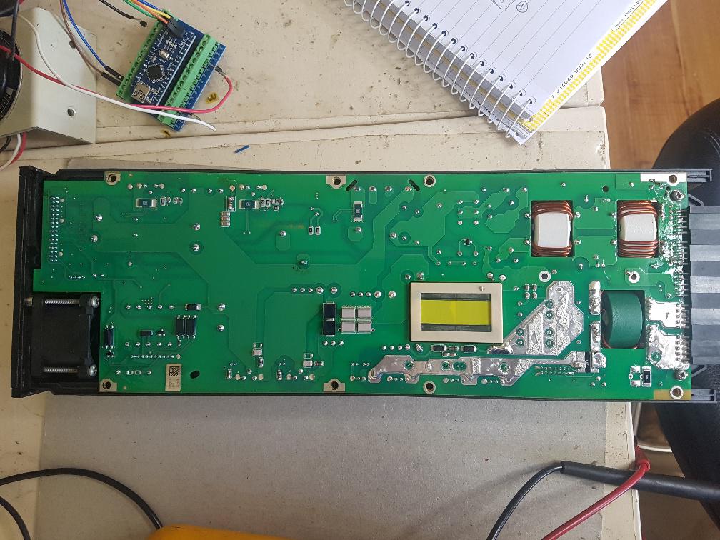 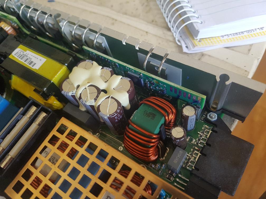 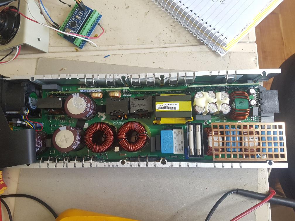 next is the DC-DC converter I think there was a repair made to it. Whether the repair was successful is an open question. 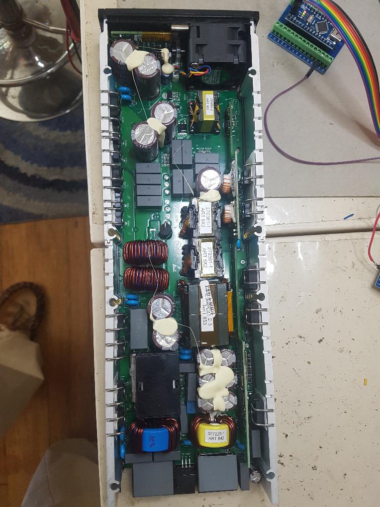 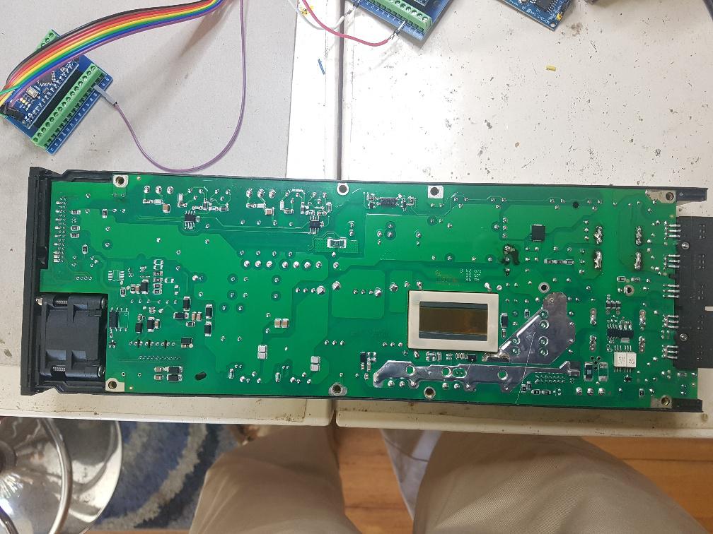 a closeup of the repair. I think things got very hot here. Also, the PCB is 4 layer to my eyes. 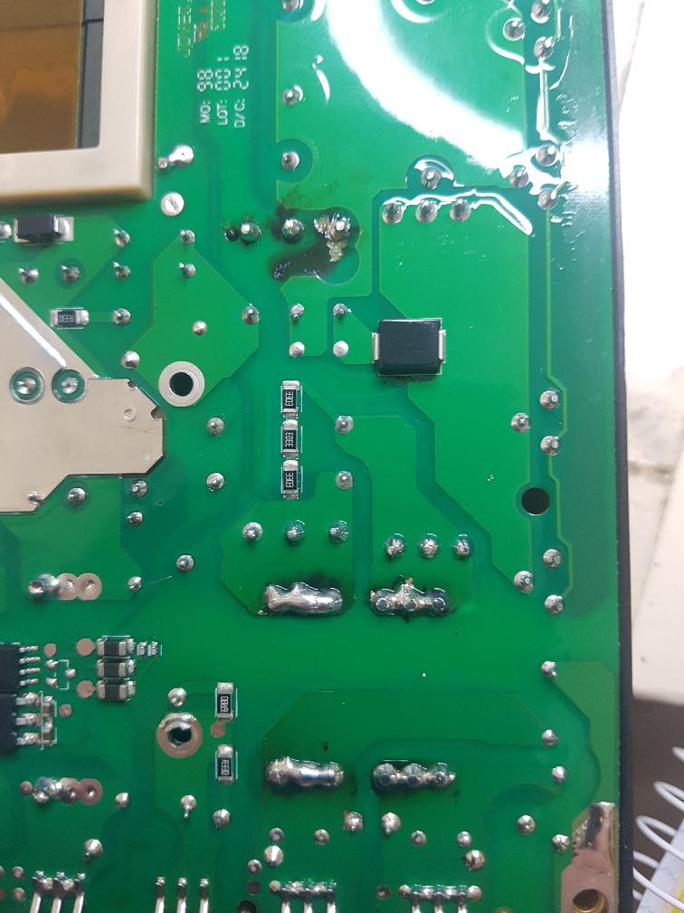 All the soldering looks as new, except on the 2 common mode choke terminals and the very average reworked 3 terminal device. Things got hot there and I doubt it got hot during soldering. 99% Tin solder is used throughout so the rework temps will be high... This area corresponds to the multiple fuse array protecting the output. There are 2 x 3 fuses in parallel under the black plastic box. I wonder if some are blown. Anyway, it only owes me $50 so I will not worry too much. wronger than a phone book full of wrong phone numbers |
||||
| disco4now Guru Joined: 18/12/2014 Location: AustraliaPosts: 1134 |
Hi @poida, What CAN library are you using to compile your code. I found a couple of different ones that give the files #include "mcp_can.h" #include <mcp_can_dfs.h> but each is slightly different on a couple of the function definitions. Regards Gerry F4 H7FotSF4xGT |
||||
| poida Guru Joined: 02/02/2017 Location: AustraliaPosts: 1481 |
Gerry: the library is, I think, CAN by Sandeep Mistry v 0.3.1 I found quite a few can libraries, but when I list what is "installed" on the imac here at home is the above. wronger than a phone book full of wrong phone numbers |
||||
| disco4now Guru Joined: 18/12/2014 Location: AustraliaPosts: 1134 |
Hi @Poida, I just received my Flatpack2 48/2000 HE, What sort of connector did you come up with. I see one made with vero-board on the other forum and also some PCBs made to do the job. 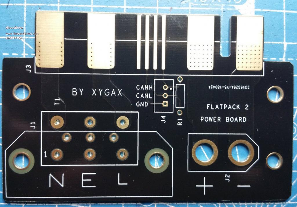 Regards Gerry F4 H7FotSF4xGT |
||||
| poida Guru Joined: 02/02/2017 Location: AustraliaPosts: 1481 |
Wiseguy sent me a PCB connector. The one shown in your post is probably the same sort of thing. the 3 pins for canbus are sort of isolated. When using them, the ground needs to be tied to output negative. And the canbus transciever needs to terminate can-hi and can-low with a resistor. There seems not to be any termination resistor within the Eltek's canbus outputs. wronger than a phone book full of wrong phone numbers |
||||
| poida Guru Joined: 02/02/2017 Location: AustraliaPosts: 1481 |
Added an LCD now. 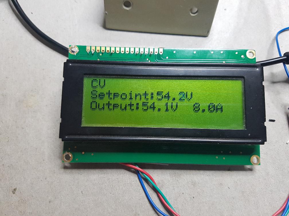 Need to add CV/CC mode switching and some warning and error messages. These may include: 3 High Mains 4 Low Mains 5 High Temp 6 Low Temp 7 Current Limit The wiring for my serial LCD is easy to do, took me 10 minutes. 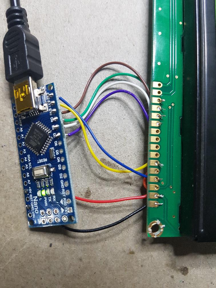 and on the other side.. 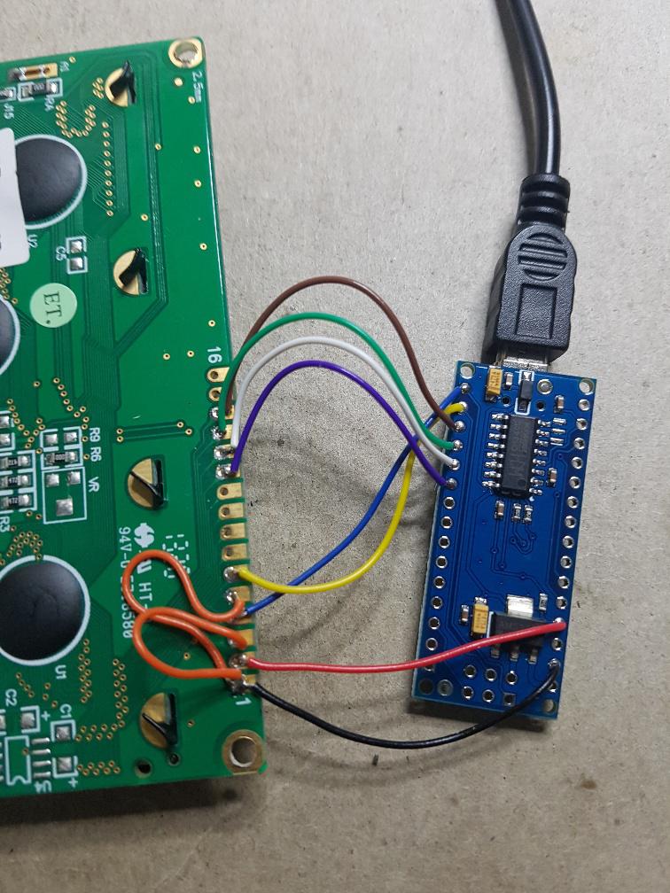 wronger than a phone book full of wrong phone numbers |
||||
| poida Guru Joined: 02/02/2017 Location: AustraliaPosts: 1481 |
The PCBs arrived from Wiseguy. This means it's time to parallel 2 Eltek Flatpack 2kW 48V supplies. The first test is CV, that is, I set the output voltage and let the current go where it pleases. The load is a modified mppt dc-dc converter that presents zero current load at 45V and max load at 56.7V input. This makes for about 2500W total load on the converter's output, rapidly bringing the water cooled resistor to a boil. pics or it didn't happen, right? 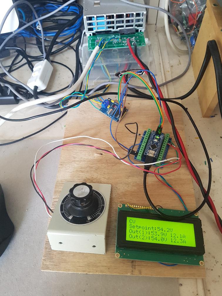 This shows the 2 Elteks and their output voltages and currents. The setpoint is in volts and is used to program both Elteks to output that voltage. The display shows Eltek PS #1 reports 53.9V and 12.1A on the output Eltek PS #2 reports 54.0V and 12.3A The canbus wiring has both Elteks parallel their can-high, can-low and can-ground pins, which are then fed into the MCP2515 module. Talking to one or the other PS is done with different canbus ID. No need for two (or more!) MCP2515 modules. The canbus standard permits multiple devices on the single bus. 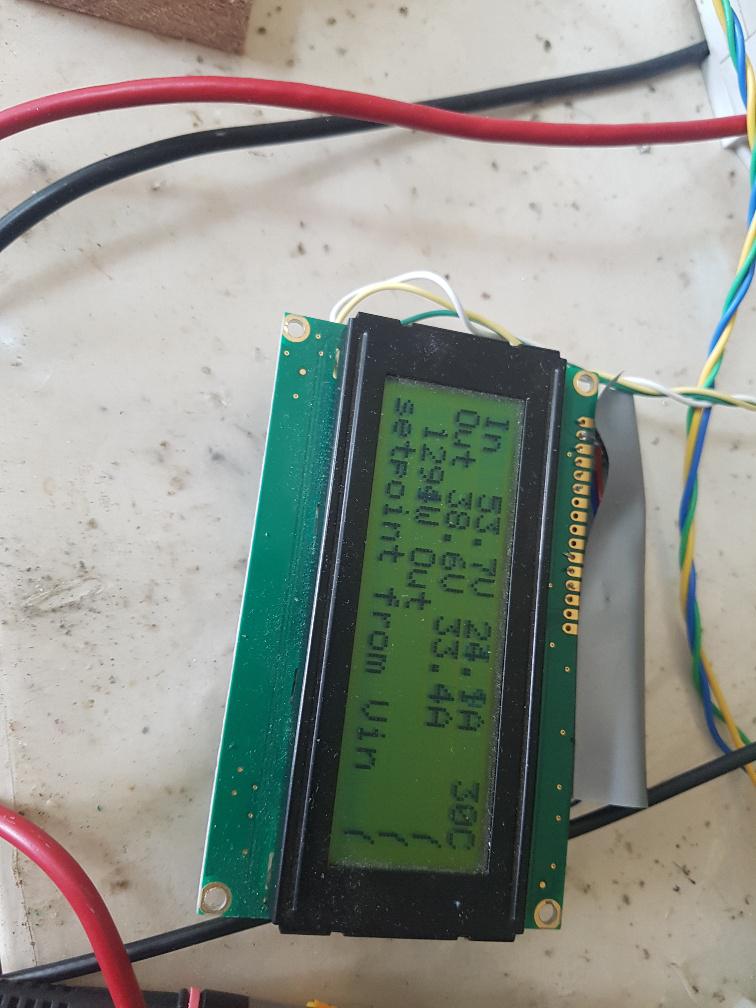 This is the display from the dc-dc converter. It shows input voltage and current as well as output information. It shows 24Amps in at 53.7V The two PSs are sharing the output. How does it go dynamically? 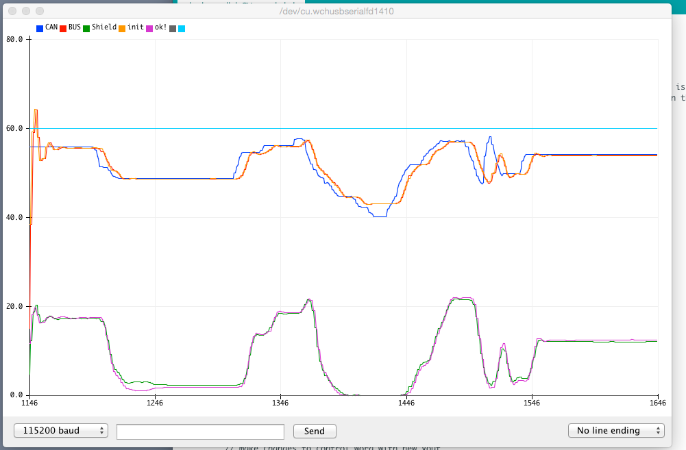 Blue is setpoint voltage. Read and Yellow are output voltages as reported by the PSs Green and Purple are output currents as reported by the PSs There are clearly differences in the closed loop control performance when tracking a voltage setpoint. This will not be able to be remedied since it's a function of Eltek firmware. But to me it looks fine. What is a couple of Amps difference in output going to matter? There are good reasons why they do not track in lockstep perfection. 1 - different DC output lead lengths 2 - different calibration from PS to PS, factory set calibration too. 3 - possibly a difference in firmware revision yielding altered PID performance. wronger than a phone book full of wrong phone numbers |
||||
| wiseguy Guru Joined: 21/06/2018 Location: AustraliaPosts: 1297 |
Excellent results Poida, looks to work a treat ! I have also been considering how to control Elteks in series and it doesnt look easy. The simplest (?) method I can come up with involves a bastardisation of the can bus. essentially it is 3 optically isolated can bus transceivers merged to a 1 of 3 or 4 switcher for the Txd & Rxd lines. The nano selects an address on 2 pins which gates up to 1 of 4 outputs. ie select can 1 talk to Eltek 1, when transaction complete select can 2 talk to Eltek 2, when transaction complete select can 3 talk to Eltek 3 etc. Because of the full duplex nature of the can bus and the complex bus arbitration required for multiple can unit comms it doesnt lend itself easily for multiple isolated nodes for talking to Elteks that have elevated voltages when they are connected in series for higher voltages. What are your (and any one else with any ideas) comments and thoughts on how to achieve comms with series connected Elteks ? If at first you dont succeed, I suggest you avoid sky diving.... Cheers Mike |
||||
| Page 1 of 5 |
|||||
| The Back Shed's forum code is written, and hosted, in Australia. | © JAQ Software 2026 |
