
|
|
Forum Index : Electronics : Newbie needs a little help with LG motor
| Author | Message | ||||
| Daniel_f Newbie Joined: 10/03/2010 Location: SwedenPosts: 8 |
Hello everyone! I recently took delivery of these 36 pole motors from LG WD-14120FD stator : 4417fa1994e rotor : 4413er1001a F1409TD stator : 4417ea1002g rotor : 4413er1001d I would very much like to find out more about their uses as generators and how to re-wire them. My intention is to build a small wind power system to produce a kWh a day with a small 12V buffer battery. I'm trying to find out how I am to re-wire the generator so that I would keep the battery charged up while supplying about 70 watt to other equipment and would like to do this at a low rpm as windspeeds give the most energy at around 4-12m/s (see appended graph). 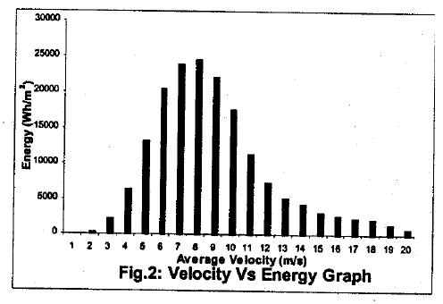
So, is there anyone on this forum that would kindly help me decide how to redo these into suitable generators? I'm pretty confident I have access to all neccessary equipment needed. It's the knowledge I lack. I will post photos of the motors soon. With best regards Daniel |
||||
| GWatPE Senior Member Joined: 01/09/2006 Location: AustraliaPosts: 2127 |
Hi Daniel, from your data, you have a very windy site. Probably even give oztules site a run for the money. For your loading requirement, and the enormous amount of energy available, you could probably get away with about a 1m^2 rotor area for a HAWT. You could probably get a VAWT to provide enough power. A low speed HAWT would need a heavily stalled rotor, with a mid sized rotor dia. You do get significant winds at 20m/s. Good windmill protection systems will need to be in place. Will need a little more info re wind energy distribution through the year to help any more. Gordon. become more energy aware |
||||
| Daniel_f Newbie Joined: 10/03/2010 Location: SwedenPosts: 8 |
Hello! I have appended the other graphs I have available for the given location. This is not the only location I'm interested in establishing a windmill though, but I haven't been able to get the data for the other location yet. But I know it is farther inland so it will naturally contain less energy, as this you're looking at is from a larger island (St.Martins, Bangladesh) close by. 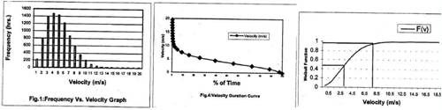
I would prefer to build a Hawt with a three or five blade design with a very simple airfoil made from large diameter Mosa bamboo. This is not much different than the popular "PVC blade" design. Resin infused blades with a core of bamboo is also possible, but not plausible as I want it simple and extremely cheap to change and manufacture oneself, on site. However, I feel stuck right now because I can't make any approximations of airfoil or size of turbine since I do not have any data from the generator its supposed to drive. I need a power and torque model and to get those I need to figure out a way to, preferably non-intrusive but accurately, obtain these. The power regulation is supposed to be by automatic mechanical furling. This seemed the simplest way of reducing swept area. Daniel |
||||
| maheanuu Newbie Joined: 08/03/2010 Location: PolynesiaPosts: 6 |
Daniel, I have emailed LG asking about both of the motors and their characteristics. I used all the information you furnished including the Stator and Rotor parts numbers for both. I am still waiting to see if them will answer me and provide any information on them. I will keep digging and perhaps I will find more information and if I do, I will post everything I can find here for you. I hope this might help ease the insecurity you are feeling at present. More later and I will post tomorrow even if I haven't heard anything. Ken |
||||
KarlJ Guru Joined: 19/05/2008 Location: AustraliaPosts: 1178 |
12V I think I'd be going for a 2 coils in series. 12 volts, high speed turbine. 36Pole 6X2C same as the F&P re-wire which unfortunately is about the most complicated time consuming re-wires of all time. At that wind site as Gordon suggests high speed 2m diameter would be plenty and yield good output my tip would be to avoid 12V if at all possible. Any of the re-wire options for the F&P on the homepage would be suitable for the LG motor. thus figure out your system voltage and go from there. In my mind BIG Bamboo should make a pretty good airfoil, with some time invested. I'd go for 6 blades so its kinda self limiting to some extent and has good startup Karl Luck favours the well prepared |
||||
| Daniel_f Newbie Joined: 10/03/2010 Location: SwedenPosts: 8 |
Wow, the response here is great! I'm looking forward to see what we can achieve here. Yes system voltage. I know there's a lot of losses having a low voltage/high current system in a small gage but long cable. Solution is to use bigger gage, but its expensive and still isn't exactly lossless. Raising the voltage to 48v makes losses apprx. 1/5 of those in a 12v system when using normal gage wire (2,5mm^2) at same length, but can I still use it to charge up a single 12v battery? Could a simple zenerdiode circuit at the battery ensure success? Examined the motors today, they seem to be wired in groups of 16 coils in series in three phases, with every coil in a phase being the third from a start point. Do not know if they are wired in delta or star.. There's also another connector which I believe is for the hall sensor. There's a couple of pictures of them appended. Would not using the motor as is for generator together with a switched power supply unit from i.e a computer allow for an effective way of transferring power practically lossless, with minimal invasion and still provide 12 volt stabilized? Switched units are designed for a varying input voltage right? D 2010-03-11_054511_Bilder.zip |
||||
| GWatPE Senior Member Joined: 01/09/2006 Location: AustraliaPosts: 2127 |
Hi Daniel, is it possible to post the middle graph by itself? Gordon. become more energy aware |
||||
| Daniel_f Newbie Joined: 10/03/2010 Location: SwedenPosts: 8 |
Ah, yes. I see it became a bit too small.2010-03-11_080429_vind.zip |
||||
| KarlJ Guru Joined: 19/05/2008 Location: AustraliaPosts: 1178 |
looking at them more carefully, you wont be giving 'tules a run for his money any time soon, looks more similar to my site but I have more than 2000hrs of 5m/s A great site meets the 80/20 rule and that is 20% of the time you'll be making peak rated power. Unfortunately, the only one we know of is OZtules who just goes outside and turns on the mill when he wants some free power any time he likes, charges up the car, few batteries etc. I used to think my site was pretty good and it sure is better than most but 80/20 is not looking promising. more like 87/13 which looses me 500KW/HR a year over the 80/20. Luck favours the well prepared |
||||
| Daniel_f Newbie Joined: 10/03/2010 Location: SwedenPosts: 8 |
Never mind wind conditions right now, I've been measuring the two motors and I won't be producing any power with these as they are. The best result I got was a peak at 500 rpm and 250 watt with a 40 Ohm load. Strangely power went down having a very small ohmic load. I'll append the results in an excel file with two "sheets". 2010-03-25_213248_LG_generator.zip The motors were tested using the two watt meter principle, eliminating the need to measure the third phase and thats why you can find columns labeled w1 and w2. The column of importance is w1+w2 which shows the total power. Since I used an old three phase ohmic load I could'nt choose how much to load exactly but adjusted it in an arbitrarily position and then calculated the load afterwards by dividing U by sqrt(3) and then using U/I=R. Now from my measurements I make no useful power during low rpms. I expect the turbine to turn somewhere from 50-300 rpm and here I have absolutely nothing to gain from using the motor as is. Can I change the motors characteristics by rewiring the coils? Some of the pages here refer to using the alt. as is for a slow turning turbine and I can see how this works having more coils in series to produce higher voltages at low rpm. But looking at what I measured its very confusing. I don't see how I would be able to get 12-14 volts and 15 amps using this? On the contrary, I found a report from cogenmicrosystems which seem to have gotten similar results as we did using a standard stator. And people here do report of getting up to 17 amps @ 12 volt (rewired), so what can be done to improve the motors performances? Does a rewiring with fewer coils in series really help improve performance at lower rpms? /Confused |
||||
Downwind Guru Joined: 09/09/2009 Location: AustraliaPosts: 2333 |
[quote]Does a rewiring with fewer coils in series really help improve performance at lower rpms?[/quote] Arrrr.....Yep it dose. You have 2 scales...voltage ...and..Amps. As volts come down with the windings amps go up. Its a hell of a lot better to have 10 amp at 14 volt compaired to 1 Amp at 140 volts into a 12 volt battery. Have a look at the front page section for stator rewires. With your wind speed a lg might not be your best option. As you will most likely drive the wheels off it. Your better option would be a AXFX like Gordon and Oztutles run. Then you can build a alt to suit your good wind conditions to the full benifit. If you have the wind then why waste it? Pete. Sometimes it just works |
||||
| Daniel_f Newbie Joined: 10/03/2010 Location: SwedenPosts: 8 |
Yes, true as you say. But my fear is that I will have 14 volts at 500+ rpms, when I would ideally want 12+ volts already at 100 rpms and a couple of amps to charge. How do I do this? If I cut the coils and rewind them into say 6X2C, is it possible from the information I have to predict how the generator will perform between 50-300 rpm or does anyone know how the curve shifts left? Also, I'm thinking about buying the rewire charts from ecoinnovation.co.nz, do you guys think it could be a good move to find out more? How do you mean when you say that I'll "drive the wheels of it" and what is that AFXF you speak of? I'm not native to english so some things are harder to get ;) Thanks /D |
||||
| Daniel_f Newbie Joined: 10/03/2010 Location: SwedenPosts: 8 |
Maybe you mean that the generator is too small to utilize all the power in the wind? The F&P should be capable of 400-500 watts and so should this unit which is enough. I'm sorry, but I really need to stress that I don't understand how the gennys power would shift towards a lower rpm band by rewiring it. I mean as of now, I get a maximum of 250 watts at 500 rpm. Shouldn't I still get this after rewiring only ie.14 volts and fitting amperage which together would add up to 250 watts again at 500 rpm? What people seem to report here is rewiring enables up to 14 volts (or higher) and 20 (!)amps. But they don't say wether this is at 200 rpms or 600. It makes a big difference since the turbine will almost never make any useful power if this would only be true for high rpms(=very high windspeeds). And I'm pretty confident you all feel your turbines makes more power than that. I do not say you're wrong, I only want to understand why it should work. D |
||||
| KarlJ Guru Joined: 19/05/2008 Location: AustraliaPosts: 1178 |
OK, what we're talking about here is two things, reactance limiting, which is the magnetic field induced by the windings as you get more power (laymans terms) this magnetic field generated cancels out the magnetic field rotating about it (the stator) and thus the output will remain constant rather than rising. Problem here is as the windspeed picks up the power available goes up by a cubic function and the output of the generator remains basically fixed this= problem as the turbine will keep accellerating until it self distructs. 2nd problem is the resistance of the windings and at a certain point (if unrewired) the resistance kills the output VERY early when running into 12V. However, by parallelling the output of sets of coils the available amps will rise significantly. Now the solution is to get the right match and the right stator. fortunately the F&P is very flexible like this and can be rewired several different ways and there ate three wire size stators to choose giving a LOT of possible combos. Save your coin on ecoinnovation post the question again next with more detail (for my benefit if you havent already done so) Stator type 60,80 or 100S System voltage required turbine type (VAWT,HAWT) and diameter. if you are running 12V i'd be aiming for 7x2C on an 80S and if you want more grunt than 250W delta is the go 500W+ and CAP voltage doubler, then you have a really useful piece of kit that handles both ends of the wind spectrum well. AXFX is a home made BIG magnet generator and cost is upwards of $1000 depending on your skill level (beyond me at this time) Karl Luck favours the well prepared |
||||
| Daniel_f Newbie Joined: 10/03/2010 Location: SwedenPosts: 8 |
Hello, so, again, perhaps more detail I've got two stators with matching rotors. Stator #1 - This stator is larger than the other with wider coils and what seems as fewer turns. Wire diameter is 1 mm. Stator #2 - This stator has 0,8mm wire. My system voltage will be 14 volts (for charging a single battery), turbine type will be a three or five blade hawt with <= 2 meter diameter. How do I rewire these LG stators for best performance during low rpms (70-300)? The larger stator would be what you refer to as a 100s and the smaller as an 80s. They are both wired into a single star configuration with every fourth coil in series just as in the F&P. The associated rotors have ferrite magnets and a total of 48 poles. The stators themselves both have a total of 36 coils. Thanks Daniel |
||||
Greenbelt Guru Joined: 11/01/2009 Location: United StatesPosts: 566 |
Daniel_f TRY THIS LINK and this oneThe Back Shed A couple Notes; The standard motor is wired to use high Voltage. when used as a generator it will produce high voltage. Power is watts, No matter what combination of volts and amps, When multiplied as the factors, result in the same units of power. 240 volts multiplied by 3 amperes = 720 Watts. 240 volts through a 12 volt battery is nearly a short circuit. 14 volts at 3 amps is 42 watts. the rest of the power(577 watts is boiling the acid in the battery an heating the coils in the alternator. A good rewire and matching mill to the load can put 40 amps at a much lower voltage (18 volts) 40 X 18 = 720 watts. 13 times more battery charging potential. The voltage drop on the Diode bridges and transmission wires will be enough to place the Charge voltage near the desired 14,5 volts. In practice this will be very difficult to achieve straight off the Mill. A devise called a voltage Regulator is very helpful in this situation. Time has proven that I am blind to the Obvious, some of the above may be True? |
||||
| carl1 Regular Member Joined: 16/04/2007 Location: AustraliaPosts: 79 |
Hi I did some test runs on the Lg. Look up my posts. cheers |
||||
| GWatPE Senior Member Joined: 01/09/2006 Location: AustraliaPosts: 2127 |
I had to break your reply up a bit. First off, this is the normal result without a rewire. OK. and in the last quote this is the solution with a rewire to match the alternator to the load. OK. In the second quote, the 577W will not as you say, "be boiling the acid in your battery and heating the coils in the alternator". The alternator iron core will reject the loading with inductive reactance limiting. The rotor will only be loaded in the case of the 14V and 3A example to about 60W, and not 720W. This is why some inductance limited mills suffer runaway in high winds. This is a difficult concept to grasp, and it is not until you have a windmill go through runaway, and not burn up, and see just how fast the blades can go, that you look for the why, and what happened to the power. Gordon. become more energy aware |
||||
| adonis Regular Member Joined: 13/02/2010 Location: SwedenPosts: 42 |
hello Gordon. I'm trying to understand what inductance is. i have a LG motor, probably the same as Daniels smaller one, the one similar to the F&P 80s. when im spinning it with full force (by hand) it kind of looses all the braking momentum for short periodes. (it's connected to a battery via a rectifier, and the voltage only rises slightly when the rotor is turned). i assume this is because of inductance? my aim is to build a small VAWT, so i dont expect to see very high rpm:s. thats why i was thinking not to rewire it, but now im not sure. the inductance problem cuts the power out already at around 3A (according to my very cheap multimeter), and that makes the motor a quite poor generator (in my case 14*3=42W max). finally to my question: is the inductance proportional only to the current in the coils? would my motor be much better if i rewired it and maby geared it up to a higher speed. or do you think your voltage doubler would take care of this problem? (i must say i still dont understand how it works, but i'm not questioning that it does). do you (ore anyone else) have any thougts or recommentations? /jonathan |
||||
| GWatPE Senior Member Joined: 01/09/2006 Location: AustraliaPosts: 2127 |
This happens when the iron core saturates, and the iron effectively has zero effect. You are left with only the flux coupling to the air cored coils, and this is very feeble, without the iron. This is why an air cored machine, like an AxFx, is desirable, as this cannot happen at peak power levels. As long as the power dissipated by the core resistance does't burn the stator, and cause a another problem. This is relatively easy to design around in a HAWT. You may get away with this with a VAWT :) due to other limiting factors, but I am only an arm chair expert wrt VAWT's. Gordon. become more energy aware |
||||
