
|
|
Forum Index : Solar : Build a Mppt 3 Kw Charge Controller
| Author | Message | ||||
| Ghost Newbie Joined: 30/03/2019 Location: NigeriaPosts: 25 |
https://github.com/LibreSolar/charge-controller-firmware am adopting this firmware , Mike you can adopt too , it's based on stm32f072 arm 48mhz processor . Am only trying to add menu and auto battery voltage selection . |
||||
| Solar Mike Guru Joined: 08/02/2015 Location: New ZealandPosts: 1125 |
Either single '4568 or pair '4115 would seem to be ok @45 amps, if you were worried about current sharing then go for the 4568 (has dual chip internally), I use them here, always prefer the to-247 packages. Cheers Mike |
||||
| Solar Mike Guru Joined: 08/02/2015 Location: New ZealandPosts: 1125 |
I had a quick look at that link, I think the software will require quite a few mods; eg Not using 1/2 bridge cpu signals, not required with external hardware sync rectifier chip. Also using an external modulator chip to achieve 100Khz PWM at 10bit resolution. Don't know if that is possible or not with the stm32, that's why I want to have a play with it. I would like to use mini-python on the stm32 if possible.... |
||||
| Ghost Newbie Joined: 30/03/2019 Location: NigeriaPosts: 25 |
Ok, thanks .. |
||||
LadyN Guru Joined: 26/01/2019 Location: United StatesPosts: 408 |
Mike, Arduino being C++ will allow you to apply all the OOP goodness you like. Now, I am not familiar with micropython on these BP but there is a micropython fork for stm32: http://micropython.org/stm32/ https://github.com/micropython/micropython/tree/master/ports/stm32 I got interested in the stm3/BP because of Andrew and tinyt. However, I can confirm that there is full micropython AND C++ support for the ESP32 - which is what I have been using. While it's possible to do inheritance in Python, I have found mixins to be more readable and usable. At competitive coding, which we do a lot of, the problems are highly suited for composition and mixins than pure inheritance. As a result I have not looked too deeply into inheritance in Python as I have in C++ so you will possibly be able to teach me that portion. In general, for these little uC, the overhead of inheritance could possibly not be worth it. This is the ESP32 I would highly recommend to you if you were interested in micropython: https://www.aliexpress.com/item/Wifi-Bluetooth-Development-Board-Antenna-ESP32-ESP-32-REV1-CH340-CH340G-MicroPython-Micr o-USB-Lithium-Battery/32846143452.html |
||||
| Ghost Newbie Joined: 30/03/2019 Location: NigeriaPosts: 25 |
But charging of batteries, does it require all these computational powers ? |
||||
| Ghost Newbie Joined: 30/03/2019 Location: NigeriaPosts: 25 |
Popular outback Chargers fm80, they used atmega644pa, 74hc74, 74hc14 and 74hc86 to generate full bridge pwm, while connecting the input of high and low side optocoupler fet driver anti-parallel , to avoid the two arm turning on the same time mistakenly ..I will soon upload their driving logics , so as we all will look at it . I also wanted to crack the hex in the atmega, to experiment, but the cost is relatively high . |
||||
| Solar Mike Guru Joined: 08/02/2015 Location: New ZealandPosts: 1125 |
Thanks, have ordered one to play with. Cheers Mike |
||||
| Solar Mike Guru Joined: 08/02/2015 Location: New ZealandPosts: 1125 |
PCB's arrived a couple of days ago, now I don't have a full circuit dia of this controller, some is in cad format, the rest on many pieces of paper; so this is the best opportunity to implement a proper cad drawing using my notes and the actual board..... what happens when you design the pcb first. Found one minor wiring mistake, cut one track and run a jumper, but looks pretty good, should be usable for testing, have also made some improvements to the pcb layout and added extra components. New schematic here 2019-05-20_222203_407_circuit.pdf Latest Gerbers 2019-05-20_222306_Gerbers_MpptCharger_4_07ov.zip All I need now is a controller to test it with, I have a few generic PIC cpu boards here, try one first. There is also a link on the pcb that allows testing without a cpu, user has manual control of PWM depth. Cheers Mike |
||||
| Ghost Newbie Joined: 30/03/2019 Location: NigeriaPosts: 25 |
How did you synchronized the synchronous switch ? Am seeing no pwm control link .. |
||||
| Solar Mike Guru Joined: 08/02/2015 Location: New ZealandPosts: 1125 |
Google IR11672, it doesn't require any external pwm. Cheers Mike |
||||
| nickskethisniks Guru Joined: 17/10/2017 Location: BelgiumPosts: 416 |
Mike are you drawing in easyeda? If you chose for "copper exposed", is it red copper or tinned? I want a tinned surface, do you know how I could do this? |
||||
| Solar Mike Guru Joined: 08/02/2015 Location: New ZealandPosts: 1125 |
I use full version of DipTrace. To have a copper area tinned, apply a Top or Bottom solder mask shape overlay, any copper tracks, or pours falling within the masks perimeter will be tinned, any silk layer items will not be printed, any vias will require their top or bottom be open rather than tented. I cannot comment for EasyEda, but it must have a similar process... Cheers Mike |
||||
| nickskethisniks Guru Joined: 17/10/2017 Location: BelgiumPosts: 416 |
Ok thank you, that helped. How is testing going on? Nick |
||||
| Solar Mike Guru Joined: 08/02/2015 Location: New ZealandPosts: 1125 |
Designing a suitable cpu controller at the moment, keep running out of cpu IO pins, so have decided to use an I2C port expander chip with 16 io's MCP23016 - which I have never played with before - for connecting the slower peripherals, eg relays, leds, setting control switches. High speed cpu IO now reserved for fast analog readings, voltages and comms etc. I also want the ability for a "Master Controller" function, so when say 3 controllers are connected to a single battery bank, there will be 1 master that controls the actions of the others, otherwise they will all go to float etc at different points. The controller also has to have an input from a BMS unit that will tell the controller to reduce its charge current to a low level so balancing can be achieved for LifePo4 banks. As for testing the power board, have made few changes (Improvements) to the layout yet again and have sent gerbers away, will get pcbs back by courier end of this week, 2oz copper this time, want to try more output current... Cheers Mike |
||||
| Ghost Newbie Joined: 30/03/2019 Location: NigeriaPosts: 25 |
Good Job |
||||
| Solar Mike Guru Joined: 08/02/2015 Location: New ZealandPosts: 1125 |
As the controller requires lots of IO's to connect to various leds, relays, temperature sensors etc and its all slow speed stuff, have decided to implement this on a separate pcb that can be mounted behind the front panel; its also pretty generic, so can be used for other projects. By using the 16bit I2C expander chip, mcp23016, this frees up CPU IO, so have more choice using a smaller device, and no haven't decided what CPU to use yet (suggestions...). The LCD display can also mount on this pcb; if I use one of those cheap 4 line 20 char ones with the I2C back pack, then it can share the same SDA\SLC bus. Noted that they all seem to use an 8bit expander chip, which means all LCD data has to be sent twice as the LCD operates in 4bit mode... really slow. As I may have multiple battery banks, require a few battery temperature sensors, its easier to multiplex them to a single analog IO, was going to use the LM35; getting really expensive now and the cheap ones on EBay etc are extremely suspect going by some comments online, so have opted for the mcp9701 linear sensor at 50c each from RS. Circuit PDF:2019-05-30_211115_I2CIO.pdf 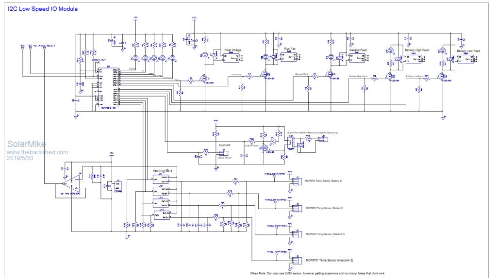 Cheers Mike |
||||
| LadyN Guru Joined: 26/01/2019 Location: United StatesPosts: 408 |
I would like to learn more about the STM32 based BP but I'm already familiar with the ESP32 and I love it because: 1. 3 cores - one ULP and 2x full speed cores 2. built in WiFi 3. RMT peripheral that will allow you to make bit perfect waveforms (just don't try bitbanging waveforms in an RTOS!) 4. I2S HIGH SPEED DAC 5. 2x ADC (which I believe has a DMA or DMA like mode?) 6. All of this wrapped up through the familiar Arduino core 7. ... all of this for $5 or less! How do I see these being useful to this brilliant MPPT charger? i. #1 ULP allows us to have minimal power draw when the MPPT charger does not need to be running without turning it off completely. The charger would not need any external batteries to run at all! ii #2 allows people with challenges like myself to monitor and automate our infrastructure. Most people won't think twice about going over to the shed and taking a peak at a cute little display to see what's going on but for me, it's a struggle to move, get up and see. My life will be significantly improved if I can view a system from my laptop or phone with BIG fonts at HIGH contrast iii. A boost or buck convertor needs bit perfect duty cycles - the RMT peripheral delivers on that as it was designed specifically for that use case. The dual cores can be doing more important stuff The rest is obvious to everyone here |
||||
| Solar Mike Guru Joined: 08/02/2015 Location: New ZealandPosts: 1125 |
Have a PCB layout for the I2C IO board, just managed to fit on a 100x100, the rear has the Leds and opto display that pokes through the front panel. 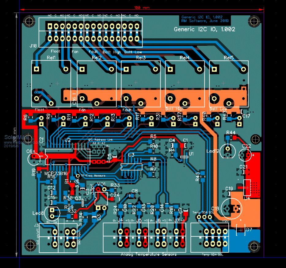 Cheers Mike |
||||
| Solar Mike Guru Joined: 08/02/2015 Location: New ZealandPosts: 1125 |
Final pcb, if anyone wants to make it, gerbers attached. Note I haven't built or tested any of this IO module, theoretical design only... 2019-06-07_194027_Gerbers_I2C_IO_Module.zip TOP: 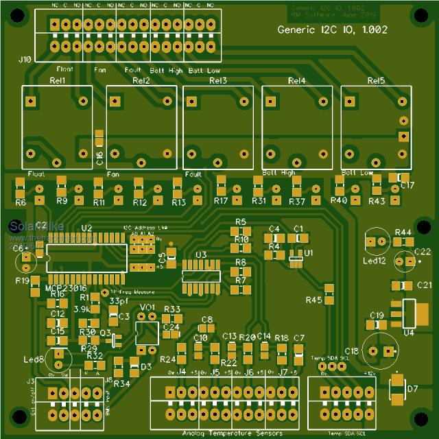 Bottom: 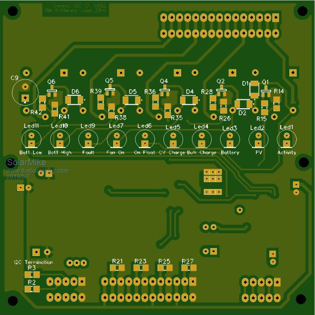 Now at last, I can get on and do the CPU board. Cheers Mike |
||||
