
|
|
Forum Index : Electronics : A newbie ozinverter build
| Page 1 of 16 |
|||||
| Author | Message | ||||
| tinyt Guru Joined: 12/11/2017 Location: United StatesPosts: 431 |
Will attempt to build this popular and great design by Oztules. If succesful, I will see if I can remove a 1.5hp pool pump (actual power draw is about 1.2KVA) from the grid. In the process, I am hoping that this old fart can still learn something. So, my first step is to draw a schematic of the power board based from the gerber that Oztules posted somewhere, probably here also.To minimize my confusion, the schematic basically follows the same viewing orientation as the gerber. I will appreciate it if anybody has the time to look at it as I always make mistakes. Thanks. 2018-02-12_151253_OZINVERTER_POWER_BOARD_SCHEMATIC5000AW.PCB.pdf |
||||
| johnmc Senior Member Joined: 21/01/2011 Location: AustraliaPosts: 282 |
Good day , Looks good I can not find the red 4.7uF 400v polyester capacitor fitted to the middle of the powerboard in between the large capacitors. Regards john johnmc |
||||
| tinyt Guru Joined: 12/11/2017 Location: United StatesPosts: 431 |
Thanks John. I have added the capacitor (silkscreen says 4 uF). Also, found that it has 4 10000 uF capacitors instead of 6 and 6 GND pads instead of 5. They are also corrected. 2018-02-12_180444_OZINVERTER_POWER_BOARD_SCHEMATIC5000AW.PCB2.pdf |
||||
| tinyt Guru Joined: 12/11/2017 Location: United StatesPosts: 431 |
Nothing new, I just combined the control schematic(page1) with the power board schematic(page2). I hope there are no mistakes. 2018-02-14_011052_Oztules_Control_PCB_and_Power_Board_Schematics.pdf |
||||
renewableMark Guru Joined: 09/12/2017 Location: AustraliaPosts: 1678 |
I wasn't aware of a OZ design that only used 4 caps, the boards I got from Clockman (recently) have 6 caps. 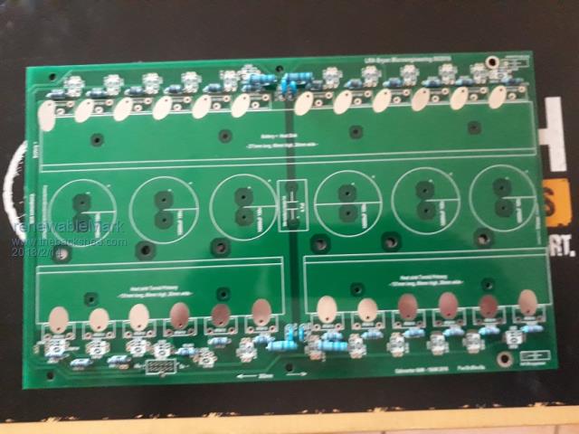 You can buy the boards here Cheers Caveman Mark Off grid eastern Melb |
||||
Madness Guru Joined: 08/10/2011 Location: AustraliaPosts: 2498 |
Oz has reduced the FETs as well to 16 in total as he is now using the beefier HY4008's rather the 4110's. Nothing wrong with 6 caps, that is what I am using. There are only 10 types of people in the world: those who understand binary, and those who don't. |
||||
| tinyt Guru Joined: 12/11/2017 Location: United StatesPosts: 431 |
Here is a GerbTool screen capture of the top silkscreen and top copper gerbers that I traced to make the schematic. 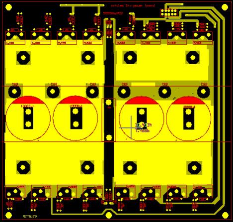 |
||||
| renewableMark Guru Joined: 09/12/2017 Location: AustraliaPosts: 1678 |
That's interesting, is it meant to be a 6kw like the one I have? Cheers Caveman Mark Off grid eastern Melb |
||||
| tinyt Guru Joined: 12/11/2017 Location: United StatesPosts: 431 |
Hi renewableMark, Good question. Silkscreen marking says 5 kw. I don't know if it was tested at higher loads. I only need to use it for a 1.2 KVA application with power coming from a 48V 100AH battery bank. |
||||
| Tinker Guru Joined: 07/11/2007 Location: AustraliaPosts: 1904 |
Should be fine for 1.2KW. 5KW would be risky unless the heat sink and cooling capacity are up to that. I'm building a 16 mosfet/ 4 capacitor inverter presently but its for 3KW. Klaus |
||||
| tinyt Guru Joined: 12/11/2017 Location: United StatesPosts: 431 |
Was comparing datasheet ratings of IRFB4110 and HY4008. IRFB4110 HY4008 Package: TO-220 TO-247 VDSS: 100V 80V ID @25C: 120A(wire bond limited) 200A(?) RDSon 3.7mohms 2.9mohms Gate Threshold: 2V(Min.) 2V (Min.) Input Capacitance: 9620 pF 7398 pF The way I understand the H bridge circuit, if the upper right mosfets are conducting, the lower left mosfets will be the conducting pair. So for the IRFB4110 (24 pcs design) 6 mosfets and the other 6 will be conducting. And for the HY4008 (16 pcs design), there will be 4 mosfets and their pair. So for the IRFB4110 design: ID = 120 x 6 = 720 Amps. RDSon = 3.7 / 6 = 0.62 mohms Input Cap. = 9620 x 6 = 57720 pF An for the HY4008 design: ID = 200 x 4 = 800 Amps. RDSon = 2.9 / 4 = 0.73 mohms Input Cap. = 7398 x 4 = 29584 pF So, based only on the mosfet choice, I think the HY4008 16 pcs design can handle slightly higher current but will be slightly warmer than the IRFB4110 24 pcs design. And the gate drive has less capacitive load for the HY4008. Please correct me if I am wrong. |
||||
| Madness Guru Joined: 08/10/2011 Location: AustraliaPosts: 2498 |
I can run over 4KW with a total of 12 HY4008's with a reasonable size heatsink, never gets over 42 degrees. There are only 10 types of people in the world: those who understand binary, and those who don't. |
||||
| tinyt Guru Joined: 12/11/2017 Location: United StatesPosts: 431 |
Hi Madness, Good to know, so I think Oztules rated his design very conservatively. What if I make provision to use a total of 20 HY4008, if the PCB is populated, maybe it can drive a humongous transformer or multiple smaller transformers. |
||||
| Madness Guru Joined: 08/10/2011 Location: AustraliaPosts: 2498 |
I have 24 in my 8KW continuous inverter which has 33% more copper than Oztules 6KW. Oztules will start a 5KW single phase induction motor, how big do you really need? There are only 10 types of people in the world: those who understand binary, and those who don't. |
||||
| tinyt Guru Joined: 12/11/2017 Location: United StatesPosts: 431 |
Hi Madness, Does your 24 HY4008 also use the IR2110 driver chips? Right now I just want to power a 1.5 hp induction motor, later maybe additional loads. Because I want to learn, I plan to make gerber files and have the PCB fabricated 2 oz copper. And since it will be a new PCB, I might as well design for bigger loads. Earlier I had problems sourcing suitable heatsinks from aliexpress and ebay. Most of them are reasonably priced, but shipping cost is expensive for me. So I thought that with more HY4008s, it can drive reasonably heavy loads with just in-efficient fabricated heatsinks from readily available aluminum, like angle bars. And if it works, maybe those in places with heatsink sourcing problems can use the PCB. The preliminary schematic is attached. 2018-02-16_025148_EXP_POWER_BOARD_SCHEMATIC_P1.pdf |
||||
| Madness Guru Joined: 08/10/2011 Location: AustraliaPosts: 2498 |
My 24 FET has the IR2110's but also has totem pole drivers on the power PCB. 1.5 hp is nothing for one of these inverters, my 12 FET version would run that all day with no problem. Our pump that supplies water to the house is nearly that big, it starts that with other things running. A quick look at your circuit looks right but I am not going to spend hours checking every last connection. Speaking from personal experience you can save yourself a whole lot of headaches by sticking to a proven design. It is not only the circuit but the layout of the tracks that matters also. As for heatsinks the ones I use, have a 10mm thick base and loys of 50mm long fins. They keep it cool but when it is working hard it needs the fans running to keep the temperature down. Trying to fabricate something out of bits of Aluminium is not going to be effective in my opinion. Try searching around electronics component suppliers in your own country. Stuff from china is cheap but freight gets way out of hand real quick, even 5 200 X 300mm 2oz PCB's costs quite a bit via DHL as they are over the weight limit for china post. I have seen people in your country say how you have suppliers there that will cut the right profile heatsinks you need to length you require. There are only 10 types of people in the world: those who understand binary, and those who don't. |
||||
| tinyt Guru Joined: 12/11/2017 Location: United StatesPosts: 431 |
Hi Madness, My primary goal is to learn. If I assemble something that is already proven and probably will work first time, I will learn some, but I think I will learn more if I start from scratch and experience and remember the agonies of fixing my mistakes along the way. Even though I am a resident of this country, parts and services are limited in my native country of which I still have relatives. They have shown interest in this project and want to build with whatever parts and services available there. Small items, I can send them but big items like the heat sink, transformer, batteries, and PV panels I cannot afford to send them. And if they encounter problems, I hope that at least I will be able to help them intelligently. Thanks for all of your good advice. I hope if I encounter problems I cannot solve, you and hopefully others will still provide guidance. |
||||
| Madness Guru Joined: 08/10/2011 Location: AustraliaPosts: 2498 |
So your a Masochist then  There are only 10 types of people in the world: those who understand binary, and those who don't. |
||||
| tinyt Guru Joined: 12/11/2017 Location: United StatesPosts: 431 |
Only if inflicted by the opposite s*x. |
||||
| Tinker Guru Joined: 07/11/2007 Location: AustraliaPosts: 1904 |
Hi tinyt, A few observations: I messed around with home built heat sinks, turned out a waste of time when one is trying to switch big loads. See if you can get hold of a junked inverter, in the 3KW or so range and extract the heat sink from it. It will almost always be still usable and might cost you nothing but dismantling time. If its a good size you could cut it to the 3 required pieces. You'll need an aluminum cutting circular blade with lubricant plus a good full face shield. Your circuit has a few components I did not use on mine but mine works well  . .As Madness mentioned, layout *is* important. This particularly implies to the high current connections. Try to supply power to the Mosfets via the heat sink (Mosfet mounting pad), you can use the big heat sink for the positive rail and the two smaller ones for the primary connections. Only the negative rail is via a PCB track, I screwed a copper bar on top of the 2oz track to carry the current easily. You can check this idea by perusing my post 'building an inverter from scratch'. Try to make the common gate track as short as you can and supply the control signal at the center of it if you can. The resistor/diode gate network should be physically as close as possible to the gate terminal. It would be remarkable if your design worked perfectly first try, mine did not  , but its all good fun and you learn a lot. , but its all good fun and you learn a lot.Just be careful, there is an awful lot of power stored in those capacitors or battery bank and the generated mains voltage also demands due respect. Klaus |
||||
| Page 1 of 16 |
|||||
