Notice. New forum software under development. It's going to miss a few functions and look a bit ugly for a while, but I'm working on it full time now as the old forum was too unstable. Couple days, all good. If you notice any issues, please contact me.
Bryan1 Guru Joined: 22/02/2006 Location: AustraliaPosts: 1206
Posted: 09:19am 02 Sep 2008
Copy link to clipboard
Print this post
Hiya Guy's,
Now I've got my digi camera back this week I'll take a pic of my cap setup- crude as it is- and now I have my voltage and current guages setup hopefully I can be there to make a movie of the current guage going haywire when the genny cuts in.
Now I'll state again my progress on deciding to try the caps.
I personally witnessed Dennis's bench tests months ago and they were using motor run caps. So I went out and bought 3 brand new 50uf 400 volt motor run caps and tried them. No gain at all. Now here I will state those blades I made that go the right way- counter clockwise- as we're downunder and the wind blows the right way where in yankie land it blows clockwise and the wrongway. Those blades are my best effort and they are exceeding my dreams as yes they have withstood 100+k winds and they are silent with no tower wobble. When I read in here about using polarised caps as non polarised I just had to try myself. My cap setup is 3 pairs of 470uf 400 volt back to back giving me between 216-219uf. I have each cap bank wired to each phase then into the rectifier. I am running a 100S in delta with no re-wiring. Last sunday it was blowing a gale and raining and I near saw the 20 amp current guage near top out and with my batteries dumping load the voltage was around 27.2-27.5 volts.In my book that is close to 500 watts and when before I put the caps on the best I ever saw was 11 amps and not long after my last bladeset went south literly so yes overspeeding.
People can knock this cap idea all they like but all I say is get off your ass - stop bein an armchair expert - and go try it. I have good working system here using caps and for all the naysayers who say this doesnt work if you aint tried it then SHUT DA **** UP and stop knocking things you know nothing about.
Cheers Bryan
KiwiJohn Guru Joined: 01/12/2005 Location: New ZealandPosts: 691
Posted: 09:59am 02 Sep 2008
Copy link to clipboard
Print this post
Bryan1, I am not knocking capacitors at all mate!
I KNOW capacitors have the potential to improve the power factor and hence efficiency of the alternator. I also know that, unless you have the luck of Old Nick, the application of a little theory will bring quicker results than cut and try experimentation. I just wish I had the expertise to do the theory.
GWatPE Senior Member Joined: 01/09/2006 Location: AustraliaPosts: 2127
Posted: 01:22pm 02 Sep 2008
Copy link to clipboard
Print this post
I expect that the RFSIM99 program may shed some light on LC interactions for the frequency ranges we need. The inductance has to be somewhere in the 20-100mH range I suspect. This will be dependent on the stator type and configuration. Lower voltage rewire gives lower inductance etc.
I will see about replicating Bryan's results. Need some more wind again. Will mount the caps in the yaw box this time.
Gordon.
become more energy aware
SparWeb Senior Member Joined: 17/04/2008 Location: CanadaPosts: 196
Posted: 06:49pm 02 Sep 2008
Copy link to clipboard
Print this post
Hi Gordon,
Could I suggest you try modelling this in WinSpice?
I used Spice to model the basic windmill system a while ago, and it really improved my understanding, rudimentary as it is.
Have you tried calculating the reactance of the capacitors at different frequencies (=rpm's)? Wouldn't that help illustrate how effective they are at different speeds?
Steven T. Fahey
KiwiJohn Guru Joined: 01/12/2005 Location: New ZealandPosts: 691
Posted: 08:20pm 02 Sep 2008
Copy link to clipboard
Print this post
Just an idea guys, considering there is more than one phase to play with it might be interesting to put different values of capacitance on each phase and compare the output in real time. Of course to do this would require a rectifier for each phase and for a three phase setup you would have three pairs of wires coming down the pole.
GWatPE Senior Member Joined: 01/09/2006 Location: AustraliaPosts: 2127
Posted: 11:09pm 02 Sep 2008
Copy link to clipboard
Print this post
I might suggest that there may be a forum reader who has an inductance meter, who could submit meaasured values for a particular configuration of F&P stator.
This would simplify the calcs.
Still not enough wind yet.
Gordon.
become more energy aware
oztules Guru Joined: 26/07/2007 Location: AustraliaPosts: 1686
Posted: 12:22am 03 Sep 2008
Copy link to clipboard
Print this post
Interesting results.
To me I would have expected in a higher inductive reactance alternator, that at higher rpm, we would naturally expect current to top out as the inductive reactance kicks in... indeed constant current output sort of result.
If we were to then drive the same alternator into a leading power factor arrangement (caps), we should see a rising rather than a lower to zero rate of climb, as the power factor straightened up.
In truth, to me it should be that with modest capacitance it is the higher end of the output that should have most to gain from a raw power perspective.
If we "tune" for this to happen earlier on, we may get an improvement at lower speeds, (what we have discussed before), but an effective short at higher rpm.
In brief, if we use high capacitance to improve cut in and low speed performance, we look to kill it off if the wind blows strongly, if we go modest with the caps to improve the power factor as inductive reactance tries to current limit, we will improve the high end output considerably, and get some perhaps useful gain in the lower speeds.
It may be interesting to test again with the same values. and then decrease these values as the wind rises. Take them out of circuit at higher power levels and see what happens. The output should droop to no more current without caps, and should continue to rise with modest values of cap.
I assume Bryan has hit on the right caps for his wind regime, and has lowered the reactance at high rpm, and has won.
I will be most interested in your final evaluation of it all, but I think it is still one size doesn't fit all... as it always is with wind.... and that doesn't address the effect of caps on blade stall with these systems either.
.....oztules ...on the fly
Edited by oztules 2008-09-04Village idiot...or... just another hack out of his depth
KiwiJohn Guru Joined: 01/12/2005 Location: New ZealandPosts: 691
Posted: 01:27am 03 Sep 2008
Copy link to clipboard
Print this post
Oztules, do you see the capacitors in series or parallel with the coils?
oztules Guru Joined: 26/07/2007 Location: AustraliaPosts: 1686
Posted: 05:16am 03 Sep 2008
Copy link to clipboard
Print this post
Kiwijohn,
It depends what we are trying to achieve. If we want to lower cutin, and perhaps sacrifice top end, I would try big caps in parallel.
If I were trying to improve top end, then modest caps in parallel.
If I wanted to drive a load (like a transformer without frequency switching to turn it on) which presents a short on the mill at idle, then series caps of substantial size (big big) would achieve the aim.
If I wanted to replace line resistance with caps then series as well, and you may also get the opportunity to pick your stall point, by planning the cap size.
All in all, I think it is not a case of bigger is better, but how you wish to match the load in your circumstance.
Zubbly experimented with the series idea for heating, and it worked well, but up in the kilowatts range, I think heating became a concern for the types of cap he employed.
I think that used judiciously, they can be of benefit to tune a poorly matched system. If a good match is already achieved, then caps won't help much, although for inductive reactance design, parallel caps may overcome reactance limiting, or at least delay it considerably, but again, suck it and see what size caps work would be my only recourse.
Any system we use to charge batteries will have power factor problems, the same as switch mode supplies cause havoc in the grid environment, and for the same reason. We don't use the whole sine wave, in fact around cut-in, very little of it, which will skew the phase relationship between the voltage and current.... at least that's how I understand it. We hog the current when over battery volts arises, and use none when below it.
I am happy to be re-educated on this as I haven't found a lot of detail on this aspect.
I am just a backyard tinkerer, and flying by the seat of your pants does not get it right first time all the time (sometimes even some of the time), but with Gordons help, I think we may all achieve a better understanding of this capacitor business. It will definitely have a place in wind generating when nothing else makes the load match work..... (ask Bryan when it does, or Bruce when it doesn't)
......oztules Edited by oztules 2008-09-04Village idiot...or... just another hack out of his depth
KiwiJohn Guru Joined: 01/12/2005 Location: New ZealandPosts: 691
Posted: 06:12am 03 Sep 2008
Copy link to clipboard
Print this post
Thanks Oztules, I should know the basics of this stuff but 40 years has dimmed it somewhat!
FandPwithPVC Regular Member Joined: 09/09/2006 Location: Posts: 64
Posted: 01:22pm 03 Sep 2008
Copy link to clipboard
Print this post
Hi All
Since I started this capaciter/condenser thing I will jump in again.
Firstly caps WILL NOT WORK on any of the non rewired F and Ps as standard units in star or delta. They create a load and this results in less output.
After rewinds or reconnecting the coils 260 rpm and more is required to start to get a 24 volt output without caps. This is unrealistic for most windmills.
However adding caps to these rewinds will give you a much lower cut in speed with the mill achieving 24 volts much sooner Up to 3 times the output is achievable if your batteries are a bit flat.
There is very little if any extra torque required to do this, it runs smoother and it is dead simple.
It works perfectly and it is not necessary to explain as to why or how. Different cap values are required for different rewinds IT IS NOT ROCKET SCIENCE
BUILT IT FIRST then criticize if you feel the need.
All for Now Dennis L
KiwiJohn Guru Joined: 01/12/2005 Location: New ZealandPosts: 691
Posted: 08:09pm 03 Sep 2008
Copy link to clipboard
Print this post
I regret Dennis that I cannot agree with all you say.
In my view, unless the AC output of the standard F&Ps has a power factor of one then any method of improving the power factor will bring an improvement.
You are quite right however when you say it is not rocket science but it is science and a bit of informed theory makes the practical experimentation go much quicker.
GWatPE Senior Member Joined: 01/09/2006 Location: AustraliaPosts: 2127
Posted: 10:23pm 03 Sep 2008
Copy link to clipboard
Print this post
Hi sparweb,
I am not familiar with Winspice. I might suggest that you publish some output graphs and some assumptions you made when you did the model.
Gordon.
become more energy aware
pntrbl Newbie Joined: 12/07/2008 Location: United StatesPosts: 32
Posted: 10:54pm 03 Sep 2008
Copy link to clipboard
Print this post
I won't pretend I'm familiar with Spice. Probably above my paygrade, , but I've been the recipient of some fabulous help from a guy at AllAboutCircuits.com that models electronic circuits with some software that's called Spice. Goes by the name of SgtWookie.
From what I gather you introduce nodes and then the various types and values of parts the nodes connect. Then you inject an input somehow and it will simulate what the output would be. And when.
I'd have to check with the Sarge to be sure but I'll bet sparweb's right in that a windmill could be modeled. Then you could change cap values all day long.
SP
GWatPE Senior Member Joined: 01/09/2006 Location: AustraliaPosts: 2127
Posted: 01:06pm 04 Sep 2008
Copy link to clipboard
Print this post
I have done some simulation with RFSim99 and tested a 100S in delta with caps at the mill head.
The inductance of the stator has a marked effect on the frequency behavior and therefore when and how capacitors work.
The work done by Dennis concluded that capacitors only worked on rewired stators. I have concluded that low inductance <10mH is best. The std 100S in delta seems to fit. All other std stators have high inductance. The most benefit appears to be for 24V NOM system with rewires where the cutin is around 200RPM. The energy stored in the capacitor has to match that of the winding for max benefit. This is matched to the optimum max RPM of the rotor. There should only be 1 optimum capacitor value for a particular rewire. The rewire will be determined by the system voltage and the TSR of the blades.
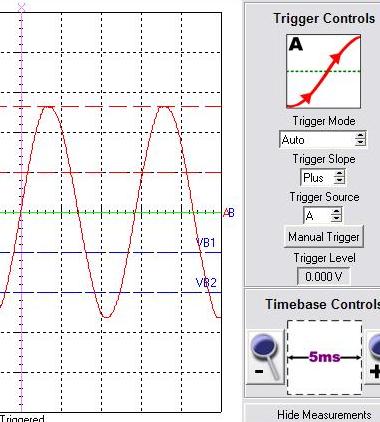
The std rotor has 56 magnets. There are 28 full flux cycles per revolution. For an individual phase, 60rpm or 1Hz rotor gives 28Hz AC output frequency. On a std 100S in delta with 230uF capacitors, cutin of 26V was measured at AC cycle wavelength of 14mS. Std 50Hz AC cycle has wavelength of 20mS therefore 14mS gives 71Hz, or 2.55 x 60 RPM = 153RPM.
How does this compare with this stator in delta without capacitors? What RPM would a 100S in delta need to produce 26V?
I hope to measure outputs at higher current levels when more winds come.
I have some oscilloscope graphs of the outputs.
This is at cutin 26V
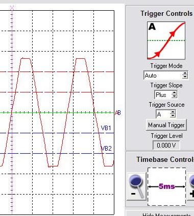
This is at an output at 2A.
Note the flat top of the sine wave output and the straightening of the sides.
The mill increased 5 RPM at the 2A power level. The normal unloaded output of the system increased 1V per 5.9RPM. There was an effective 0.85V extra to produce 2A. The capacitor combination gives an effective delta wiring resistance of 0.42ohms. I have not measured the DC resistance of the delta combination of 100S windings, but another reader may have done this for comparison.
The current was a total of 2A for the 3phases. The RMS current that was output per phase occurred during a very short time interval. This shows the problem I have mentioned with sine waves and peak currents with a battery load. The wire has a much higher current than the average current. This is most probably why generators, including axial flux machines and iron cored machines that produce sine waves dissipate more heat than calculated when supplying a battery load.
It will be interested to see how the rpm continues to increase with higher power output? I suspect that the peak currents in the coils generate a substantial voltage drop that lowers the relative loading of the mill at higher power levels and allow the blades to sort of track windspeed. The sine wave output has a similar effect to adding resistance to the transmission line to increase power output, by allowing rpm to increase and hence reduce the chance of blade stalling. I think this was the sponginess I described earlier.
I may be wrong, but, in this case blade efficiency seems to be increased at the expense of alternator losses at higher power levels.
Gordon.
become more energy aware
SparWeb Senior Member Joined: 17/04/2008 Location: CanadaPosts: 196
Posted: 04:43am 05 Sep 2008
Copy link to clipboard
Print this post
Hi,
I suggested WinSpice because as I experimented with it, I found that it has plenty of modelling and graphing capabilities, plus it looks really nice...
Bear in mind, it only models the electrical parameters - it's up to you to figure out how the windmill system actually behaves under these conditions.
Steven T. Fahey
Bryan1 Guru Joined: 22/02/2006 Location: AustraliaPosts: 1206
Posted: 09:48am 05 Sep 2008
Copy link to clipboard
Print this post
Well KiwiJohn I'll agree with you there mate and Dennis you say a F&P WON'T work with a 100S NON RE-WIRED I suggest you local guys take a venture upto my place and I'll show you a 100S unmodified in delta working with my caps. To say I got the perfect balance is pure luck more than prior thinking on equations.
I'll state my findings again--- I was wondering why my F&P wasn't putting any real amps when the AC voltage was around 22-25 volts and my batterybanks were on 25 volts. The best I really saw was 3-4 amps and shortly after the non-cap thread got going I put those 400 volt caps in back to back config. The next time the wind blew hard I blew a fuse in my $10 DMM suggesting YES the genny is inputting better amps This made me install my analogue guages to I can see in real time what my wind genny and PV are doing. Ever since then when the wind does blow my missus says my genny has been making a heap of noise today so I usually go look at the guages and yes the genny is helping to keep my 700AH batterybank charged.
So Dennis if your so inclined to disprove 100s in delta with caps I'm sorry mate your wrong.
Cheers Bryan ( Friday night and time for another steak & egg's in my next VB )
GWatPE Senior Member Joined: 01/09/2006 Location: AustraliaPosts: 2127
Posted: 12:45pm 05 Sep 2008
Copy link to clipboard
Print this post
Hi sparweb,
The graphs I have presented, are actual measured outputs between phases.
On the simulations you present, I see no inductance values for the coils.
I used a spreadsheet to get graphs like the ones produced by winspice. RFsim99 gives more frequency related information.
Hi Bryan,
I am in the process of making an 80 series rewire. This will be a standard 2S7P star arrangement. The 80 series has a more uniform cogging feel. I will compare starting torque before and after pole twisting on this stator to the 100 series.
The pole twisting on the 100 series reduced the startup power by a factor of 4. My axial flux was producing 50W when the F&P started to spin prior to pole twisting. This reduced to around 12W when the poles were twisted. I hope to see the same result with the 80 series.
I believe that the work Dennis has done with capacitors has laid the ground work for others. I would not be too critical wrt 100 series stators. These are not common units. Dennis has tested on a stator accessable to most people.
I have found that 230uF capacitors between the phases have allowed my mill to produce useful power in delta, where I had to wire in star without caps. The cutin in star is at a slightly lower rpm. The mill will provide more power to the load in delta as there is less heating in the windings for the same output current.
A major benefit with the lower mill resistance is the stronger shutdown torque offered by the windings.
I am waiting for some stronger winds for higher power level testing.
Gordon.
PS edit. My 100S in delta with 230uF caps with twisted poles has a low whir sound as it starts up and the sound diminishes as the current increases.Edited by GWatPE 2008-09-06become more energy aware
FandPwithPVC Regular Member Joined: 09/09/2006 Location: Posts: 64
Posted: 03:09am 06 Sep 2008
Copy link to clipboard
Print this post
Hi All
If I was rite or rong is unimportant as some newer people have taken the bait and are now actually playing with the subject . MISSION ACCOMPLISHED
Please don,t allow the replies to drift into long winded highly technical goobledegoop as most of us do not understand that stuff.
THE PRACTICAL BITS ARE ALL THAT MATTER SO KEEP IT SIMPLE
Regards Dennis L
oztules Guru Joined: 26/07/2007 Location: AustraliaPosts: 1686
Posted: 02:42am 07 Sep 2008
Copy link to clipboard
Print this post
Dennis,
I understand your position on this, but some have tried caps, and they haven't worked as advertised.
It is because of this that some work is necessary to determine what really is going on here, and how best to utilise caps, if at all.
We all seem to have opinions on this, and the only way to deal with it is to experiment empirically to determine the outcomes with some reliability, and to help those on whose systems it did not give the expected result.
Just ignore the gobbldygook bits for the moment, and I'm sure something good will come out of Gordons experiments.
If we can learn what to do in different circumstances to get caps to be useful for everyone with iron cored mills, then I think you can well say "Mission Accomplished", but while some suffer disappointing or unexpected results, we need to continue to learn the why and how...... at least thats how I see it.
........oztulesVillage idiot...or... just another hack out of his depth


 Those blades are my best effort and they are exceeding my dreams as yes they have withstood 100+k winds and they are silent with no tower wobble. When I read in here about using polarised caps as non polarised I just had to try myself. My cap setup is 3 pairs of 470uf 400 volt back to back giving me between 216-219uf. I have each cap bank wired to each phase then into the rectifier. I am running a 100S in delta with no re-wiring. Last sunday it was blowing a gale and raining and I near saw the 20 amp current guage near top out and with my batteries dumping load the voltage was around 27.2-27.5 volts.In my book that is close to 500 watts and when before I put the caps on the best I ever saw was 11 amps and not long after my last bladeset went south literly so yes overspeeding.


 , but I've been the recipient of some fabulous help from a guy at AllAboutCircuits.com that models electronic circuits with some software that's called Spice. Goes by the name of SgtWookie.
 I suggest you local guys take a venture upto my place and I'll show you a 100S unmodified in delta working with my caps. To say I got the perfect balance is pure luck more than prior thinking on equations.
 This made me install my analogue guages to I can see in real time what my wind genny and PV are doing. Ever since then when the wind does blow my missus says my genny has been making a heap of noise today so I usually go look at the guages and yes the genny is helping to keep my 700AH batterybank charged.