
|
|
Forum Index : Electronics : Nano Power Inverter - Roll Your Own Style
| Author | Message | ||||
| wiseguy Guru Joined: 21/06/2018 Location: AustraliaPosts: 997 |
Thanks Andrew I guess I'm just disappointed that I might still have to wind something for 8 - 10kW - was hoping I had dodged that bullet. It was easy to figure out that he didn't know what he was selling - and I had a fair idea what I was getting, but I had just hoped he was right.... The data from the transformer testing is posted below. 2019-05-22_183627_Toroidal_Performance_Data.pdf Later as an experiment I put one diode in series with the mains and 3 in series inverse parallel to the first diode. I wanted to introduce a dc offset to see what happens if the two halves of the sinusoid are not exactly equal. it gave some interesting results that I dont fully understand. I used the Aerosharp transformer. At 57V in the current measured 66mA - more than at 250V without the diodes offset. At 102V in the current was 240mA and peaked at times at 1.2A at turn on. The surprising part was the true power was only 4.4W - I was expecting ~10 times that. So we have heavy circulating currents but little power being used (absorbed) - I expected driving the transformer towards saturation would have been more wasted power than I experienced. I look forward to professor Warps take on all of this - over to you Tony ! If at first you dont succeed, I suggest you avoid sky diving.... Cheers Mike |
||||
| Warpspeed Guru Joined: 09/08/2007 Location: AustraliaPosts: 4406 |
That's a pretty interesting observation Mike. Driving the transformer asymmetrically will certainly tend towards a form of staircase saturation in one direction, but the interesting thing is that almost all that stored energy appears to be returned back to the source on the opposite half cycle. So as you say, mostly just circulating current, but no real power being dissipated. If you think about it, its only milliamps, and the ohmic resistance of a monster like that will be rather low, so the resistive losses are going to be low too. Cheers, �Tony. |
||||
| wiseguy Guru Joined: 21/06/2018 Location: AustraliaPosts: 997 |
It may not be as benign as it appears - I can say I was a bit scared at the quantum current jumps whilst slowly advancing the variac. Like 80ma to 220ma in less than 2V sometimes it just stayed there other times another 1 volt up would reduce current quite a bit and another volt up current back to another high value. It was so unpredictable I did not push it over 135V. Maybe tomorrow I will get braver, put a perspex shield between me and the diodes and give it a heap more - they were only 1 amp diodes and I hate stuff going bang in my face..... I like the low idling current of the 2 transformers - they must have a few extra turns to keep the flux a bit lower ? Maybe all that circulating current can make FETs work real hard but this is not indicated on a supply current meter so you might have no idea that its actually occurring ? I also remember reading about transformer "hum" quality changing during idling etc. Maybe the flux does walk a bit under certain conditions ? If at first you dont succeed, I suggest you avoid sky diving.... Cheers Mike |
||||
renewableMark Guru Joined: 09/12/2017 Location: AustraliaPosts: 1678 |
$180 is small change in the scheme of a big reliable system. Cheers Caveman Mark Off grid eastern Melb |
||||
| BenandAmber Guru Joined: 16/02/2019 Location: United StatesPosts: 961 |
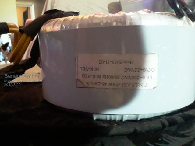 The picture above on top of this page looks just like a power Jack Transformer I would almost bet they're made by the same company The transformer in this picture is out of a 8000 Watt 48 volt Power Jack And I am guessing it weighs 25 to 30 pound be warned i am good parrot but Dumber than a box of rocks |
||||
| nickskethisniks Guru Joined: 17/10/2017 Location: BelgiumPosts: 413 |
5,years ago I paid 270� for 3 used isolation Transformers, they were 2000VA each, 17kg each, I felt it was a bargain. Amplimo is selling these for 295�/pcs new.... I had to buy copper wire though, to get a reasonable price I had to buy 42kg bobin for around 600�, I didnt want to resuse the old wire. I still have one transformer and plenty of wire. I rewired 2 Transformers for +/-9000VA output. For my next project (warpverter) I bought 14 old Broken inverters for 850�, I'm still waiting for those. Normally they have at least 2000VA Transformers in it. I still have wire left.I hope to repair a few to regain some budget. |
||||
| wiseguy Guru Joined: 21/06/2018 Location: AustraliaPosts: 997 |
Mine was built in the southern hemisphere its the right way up lol. I do agree that if they didnt come from the same factory I would be very surprised. - I also liked your analogy of a swing to an AC resonance circuit - you are starting to get this electronic stuff, keep it up ! If at first you dont succeed, I suggest you avoid sky diving.... Cheers Mike |
||||
| BenandAmber Guru Joined: 16/02/2019 Location: United StatesPosts: 961 |
Wiseguy coming from a great like you that means a lot thank you so very much for the kind words Cracked out laughing about the upside down transformer Did you come up with a good estimate on the wattage of the Transformers I do think I have the exact same one as you Amber is giving this one to ladyN and the info might help her figure out how she's going to use it in her warp speed inverter be warned i am good parrot but Dumber than a box of rocks |
||||
| wiseguy Guru Joined: 21/06/2018 Location: AustraliaPosts: 997 |
Quick update to my inverter build, boards are all coming together with no unsolvable issues yet. Gate drive circuit with negative bias also seems to work very well. I have a few jobs on the go so, my inverter time is limited at the moment. A few pictures to show effects of gate resistor. . I found the suggestion of how to choose the correct value from an application note I found. Please ignore the CH2 volts - I had bumped the probe to x1 so 4th image CH2 is actually 2V/Div not 20. Also note the negative 5V idle bias to ~ +12V drive swing. Too low (1 Ohm) overshoot 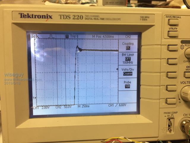 Too high (3.3 Ohm) undershoot 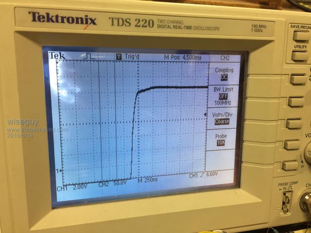 What appears to be optimum (2.2 Ohm) 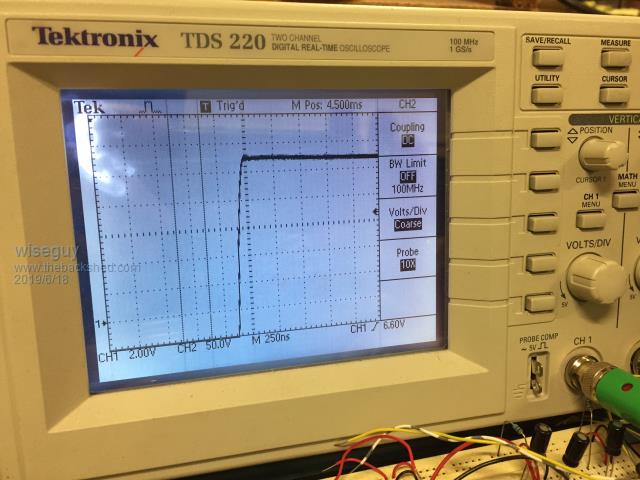 The last picture chows the 2 x drive waveforms, 1 straight at the buffered output and 2 the actual gate waveform after the gate resistor, all gates being driven (4) It looks pretty promising so far. 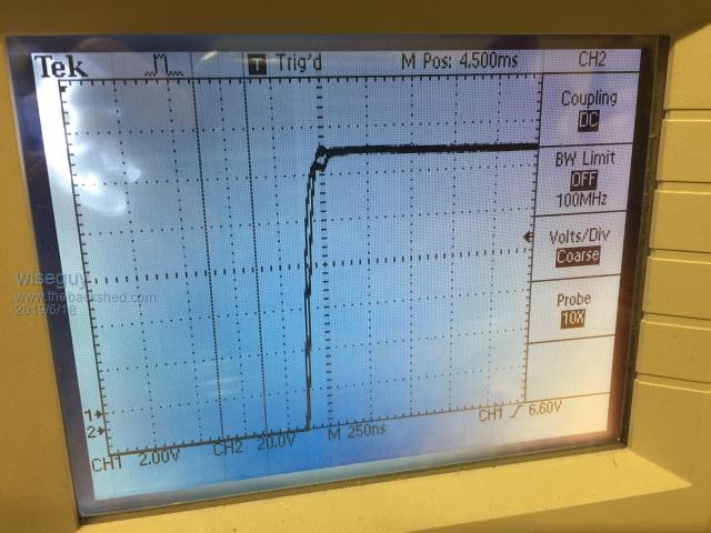 PCB with FETs mounted. 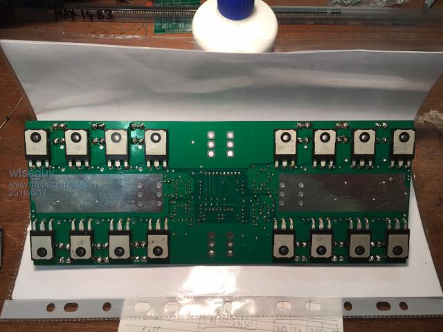 Next job is to fit the ferrite beads and select the dead-time capacitor and more testing. If at first you dont succeed, I suggest you avoid sky diving.... Cheers Mike |
||||
| Tinker Guru Joined: 07/11/2007 Location: AustraliaPosts: 1904 |
Interesting, that low gate resistor value. All of mine are twice that or more. Have to try a smaller 2R2 resistor next time. Just out of interest, are you bolting that board to a single heat sink with using Mosfet insulating washers or are you using 3 heat sinks? I suppose the ground plane keeps the top of the MosFets cool or the PCB warm  . . Klaus |
||||
| wiseguy Guru Joined: 21/06/2018 Location: AustraliaPosts: 997 |
You are correct I could use 3 heatsinks but I have chosen one for this assembly. 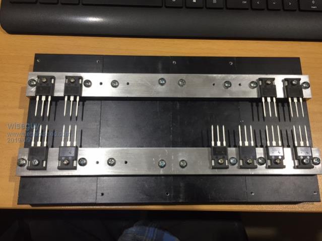 The ground planes are on both sides of the PCB. Here is the front side of the PCB, all current carrying planes are actually double width (& area) to what you see on one side. The silver areas are just a part of the total area so I could increase current capacity by soldering extra copper conductors where possible. 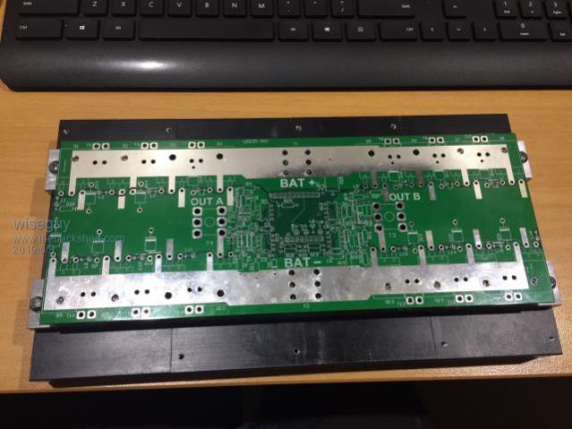 Due to the fast switching I need ferrites between each drain connection and the external connections, so connecting the drains directly to the heatsinks would not allow that. If your inveter is working ok I dont advocate to change the gate resistor to 2R2, this suits my fast buffer and PCB layout for fast switching. It may cause other unintended issues to appear on different circuits and layouts. Using a good fast CRO on the bench when not driving a load is the best way to see the effect of changing the gate resistor values - but it might cause oscillation issues to appear too. If at first you dont succeed, I suggest you avoid sky diving.... Cheers Mike |
||||
| wiseguy Guru Joined: 21/06/2018 Location: AustraliaPosts: 997 |
Time for an update on my inverter. Had some surgery to my finger a few weeks ago and haven't achieved a lot one handed since.... Have fitted all the Mosfets, insulating pads and ferrite beads. I wasn't sure when I designed the PCB whether I would have a fully isolated heatsink or connect it to Battery Neg. I decided to ground it to Bat neg & used the lower FETs mounting screws to achieve this via the PCB ground-plane. The upper row of FETs required an insulating shoulder washer so the Batt+ ground-plane was not shorted to ground also. The Enphase solar battery I recently acquired was only a 24V LiFePO4 not 48V so my testing will soon move to a 24V inverter configuration. By having a fully isolated gate power supply & opto drive I can use any input voltage to the Power board from 0 - 60V, I only need to change the transformer and choke. Obviously voltages below 12V are very useless except for initial power up & anti-smoke testing. Running from a 30V 3A bench supply it all actually appears to works very well so far with an 18V primary transformer. Today I might have bagged a good bargain on Ebay, it is a 10KW 3Phase to 48V @ 210A rectifier unit. They claim brand new never used for $75!. All in a 3u High ~ 5" rack module @ 32kG lol. I used the buy it now button - just need to figure out how to get it to SA as its in Sydney & he wanted collect, no postage. For interest here is the brochure :2019-07-14_141706_PFM10kW.pdf That should help with testing my inverter and later I can use it as a fast charger when I eventually get batteries. Update pictures below: 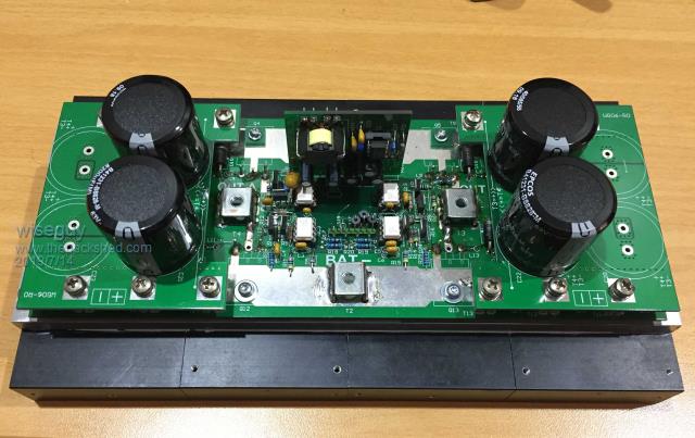 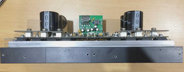 If at first you dont succeed, I suggest you avoid sky diving.... Cheers Mike |
||||
mackoffgrid Guru Joined: 13/03/2017 Location: AustraliaPosts: 460 |
Well done on the rectifier  Your inverter is looking very impressive, very neat. Would you mind posting a few photos with the capacitor boards removed. I hope your finger is mending well. Cheers Andrew |
||||
| wiseguy Guru Joined: 21/06/2018 Location: AustraliaPosts: 997 |
Dammit Andrew the capacitor boards are hiding a stuff up !  Q2's gate was not supposed to be unmasked - it was supposed to be the drain....the perils of copy paste. Ok here is a picture opened up - not sure what kinky parts you wanted to see. If you want the PCB off its only another 16 screws.... The Lower FET drains are passed through a ferrite bead and solder directly to the underside choke ground planes, that is why the holes are empty - I wanted to try it without beads first to prove that they are required. The upper FETs drains also required beads. Pardon the high rel uncleaned soldering...... 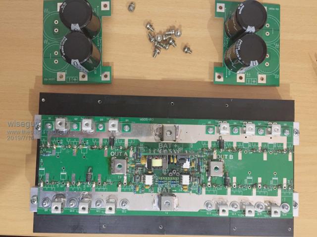 Why are the jpgs so poor what picture file format gives the best results? PS thanks, the finger is slowly mending. If at first you dont succeed, I suggest you avoid sky diving.... Cheers Mike |
||||
| mackoffgrid Guru Joined: 13/03/2017 Location: AustraliaPosts: 460 |
I think PNG format is probably the best but I'm no expert in this regard. I just like how you've put this together. I forum seems to reduce the resolution and size of the photos. I like to see the photos like you have done but if you like, upload a zip file of better resolution photos. I'm still trying to see how the bottom board and mosfets are fixed to the Heatsink. I'll re-read the thread and I'm sure my light globe will light up PS, I just like Inverter Porn  |
||||
| wiseguy Guru Joined: 21/06/2018 Location: AustraliaPosts: 997 |
The FETs are sandwiched between the PCB (face down) and an aluminium bar that has an adhesive insulator to the FET faces. The bar is threaded for all the FETs and a single screw through the PCB for each FET rigidly retains it all. The Bar is held by two separate screws to each of the 4 heatsinks - I had plenty to use up! The screws for the high side FETs are all insulated from the positive plane with a small TO220 mounting bush also with a little square pcb spreader washer. The lower side screws are not insulated and connect the Batt- to the heatsink. Here are the zipped up pics for better clarity. My viewer has every format except PNG - like me its old.... 2019-07-14_210604_PWR_Pics.zip I dont have my allen keys handy but I will dismantle it & take a few more pictures and post them soon. If at first you dont succeed, I suggest you avoid sky diving.... Cheers Mike |
||||
| mackoffgrid Guru Joined: 13/03/2017 Location: AustraliaPosts: 460 |
Your Zip photos were good thanks. I look forward to more photos after you dismantle it. Would I be right in saying you don't need the aluminium bar if you had one big heatsink? Or do you require the clearance? Cheers Andrew |
||||
| wiseguy Guru Joined: 21/06/2018 Location: AustraliaPosts: 997 |
Hi Andrew (& all), I reckon you grew cobwebs waiting for an answer - sorry for the tardy response, life & the new house took over for a while. I used the aluminium bar partly because I had lots of it. I prefer to drill and tap a length of bar and then just use a few tapped holes to hold the assembled bar complete with pcb onto the heatsink. It also allows me to run up to full power for brief periods without having a full heatsink attached. If ferrite beads were needed it also helped with clearance. Another reason is that I have a heap of those separate heatsinks and the aluminium bar holds everything together very well The 10kW rectifier has been shelved as I cant make it work on single phase and I dont have 3phase on this house. In a couple of months I will be in the new house with 3 phase available and then I will continue with it. In the meantime I bought a couple of brand new Eltek flatpack2 rectifiers for $100ea they can supply 2kW of power at 48V and can be paralleled. They use a rear connector that accepts the edge of a small pcb for 240VAC in and 48VDC out, so I fabricated a suitable 2oz connector PCB and will soon be able to power them up when they arrive here from JL. For me, as I dont yet have batteries it is critical to have a reliable & stable voltage & power reference source to enable me to continue with any meaningful testing. If I make small circuit/choke etc changes I want to know even the small resultant changes in efficiency at low medium and high power levels to know if I am heading in the right direction. If I do get it wrong, the resultant fault currents are likely to be much lower and do much less overall damage than a string of batteries just itching to release black smoke and flying plastic bits from something unsuspecting.... If at first you dont succeed, I suggest you avoid sky diving.... Cheers Mike |
||||
| renewableMark Guru Joined: 09/12/2017 Location: AustraliaPosts: 1678 |
Wiseguy re those flatpack units, you could feed them from a gen to charge batteries yeah? Monitor the charge state manually, or better yet, feed an mppt controller. I see the HE version has a higher voltage range (better suited for mppt) $100 is a good price for that, where from? Cheers Caveman Mark Off grid eastern Melb |
||||
| wiseguy Guru Joined: 21/06/2018 Location: AustraliaPosts: 997 |
Hi Mark, I bought the HE versions there are also SHE (Super High efficiency) units available but they are a bit dearer. The main difference is peak efficiency of 96% versus 97.8%. Here are the Datasheets to save people searching Flatpack2 HE_2KW48V.pdf Flatpack2_SHE_2KW48V.pdf Im quite happy for the brand new 96% units @ $100. I brought them from an ebay supplier here who said he can get more, although currently he does not show any of these for sale - it would be worth an email to him. I was so tempted to buy his remaining 5 when I saw them but didnt want to incur any wrath from SWMBO. Their output voltages for the HE & SHE are both 43.5 to 57.6V adjustable with a controller - the ebay seller pre-sets them to 48V before shipment. If you google VK4ghz there is a project for a controller for these units using their canbus. I'm in the process of building one up. They are essentially built for battery charging and there is software available & prebuilt Eltek controllers to manage them off the shelf. They should work fine from a generator and can supply output all the way from 85 - 300 VAC / 85 - 275 VDC, but at reduced power below ~ 185VAC. Edited 2019-09-12 12:42 by wiseguy If at first you dont succeed, I suggest you avoid sky diving.... Cheers Mike |
||||
