
|
|
Forum Index : Microcontroller and PC projects : CMM2: Recommendations for joystick/game controller I/F standard
| Author | Message | ||||
| capsikin Guru Joined: 30/06/2020 Location: AustraliaPosts: 341 |
I don't know that there's anyone writing paddle games or wanting to make paddles and paddle interfaces, or buy paddles to play paddle games, and that could be needed to establish common use standard. Though you'd suggested making a paddle interface yourself - were you also thinking of making paddles? Maybe using the x1 and x2 axis from the analogue joystick lines in your and vegipete's pin assignment could work, with the same voltage range. This wouldn't be compatible with old atari paddles though, as vegipete said they're a bit different. update: I just noticed the colour invaders (for the older colour maximite) game I found for someone had instructions for wiring up a potentiometer paddle, and you'd built a paddle for that. If anyone's planning on porting that to the colour maximite 2 it would be good to standardise pin assignment, voltage and signal meaning for that. Maybe the same as it already used except for input pin assignment - I think the voltage meaning is along the lines I was already thinking. But do you know which of left/anti-clockwise and right/clockwise were high and low voltage? Edited 2020-07-24 18:43 by capsikin |
||||
Quazee137 Guru Joined: 07/08/2016 Location: United StatesPosts: 522 |
Here is a two port adapter. Both ports will use the same code just need to tell the PCA9540 which one your talking with. 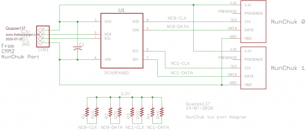 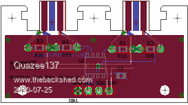 When I get bit more time again will do one using MAX11611 12 channel ADC. That is 12 inputs that can be three xyz pots and nine buttons. I think the 1st run at this one I'll just get the chip and pads so it will be a test base for any who want to play with it. have FUN and be SAFE. I sure am  Quazee137 |
||||
| Turbo46 Guru Joined: 24/12/2017 Location: AustraliaPosts: 1593 |
That's exactly why I built one. Useful for Pong or Bricks and similar. Great for small kids (and big ones  ). ).Bill Keep safe. Live long and prosper. |
||||
| mclout999 Guru Joined: 05/07/2020 Location: United StatesPosts: 430 |
https://tinyurl.com/y6qss7vz I did get on of those PS3 to WII adapter (Mayflash) on FleaBay and it works wonderfully. It thurns out that I have 9 PS2 Controllers and 3 Wireless ones as well. ĀThey all work flawlessly with a few caveats. ĀIt maps all buttions and analong stick mostly correct to Classic controller including simulating the analog Z trigers as max analog number when the digital buttons is actuated. (PS2 controllers have on analog functions in the Triggers) On about half if my controllers it switches the L and R shoulder with the corresponding Z buttons and the simulated Analog is on the L and R buttons and not of the Z buttons. ĀNo big deal and I get to use some of my all-time faroite controllers. ĀOh, one other thing it does also map L3 and R3 together as HOME even though the home button works as expected. Some PS2 controllers do not have a button for home so they also map it that way. ĀLast feature to note is it can turn Turbo on any Button and that work too. I like this thing a lot. https://tinyurl.com/y6qss7vz Edited 2020-08-01 08:06 by mclout999 |
||||
| Quazee137 Guru Joined: 07/08/2016 Location: United StatesPosts: 522 |
Just in case any one wants to play with this. I think the front NunChuk port could work doing this with a csub. Gamecube Controller Interface |
||||
vegipete Guru Joined: 29/01/2013 Location: CanadaPosts: 1082 |
I've been hacking together a game from the olden days that plays most easily with a paddle. I used joystick 2 y-axis and button D. This is convenient because analog-Y2/button-D/ground are together in a row (pins 26/28/30.) Add 3.3v from pin 40 or 24 to complete the potentiometer voltage divider. I did have to re-wire the ancient Apple][ paddle I used to get a fourth wire for 3.3 volts but a length of telephone cord was perfect. I'm not saying that a paddle _must_ be on analog pin 26; that's just what I used. Games like Pong would benefit from 2 paddles. Maybe the default choice is a joystick first on pins 7/13/32/33 and a pair of paddles first on pins 15/26/27/28. If you need two joysticks, you replace the paddles. If you need more paddles, you replace the joystick. Visit Vegipete's *Mite Library for cool programs. |
||||
| capsikin Guru Joined: 30/06/2020 Location: AustraliaPosts: 341 |
That pin 40 or 24 is pin 1 or 17 in the pin numbering system we've been using for the other pins, right? |
||||
| capsikin Guru Joined: 30/06/2020 Location: AustraliaPosts: 341 |
For now I'll be connecting my joystick right connector to pin 29 or 31 with a movable lead, but leaving in support for pin 40. New sample code: If (Pin(40) = 0 Or Pin(29) = 0 Or Pin(31) = 0 Or keypressed = 131) Then GoRight = 1 |
||||
| vegipete Guru Joined: 29/01/2013 Location: CanadaPosts: 1082 |
I'm basing pin numbering on what's printed on the bottom side of my (Waveshare based) CMM2 board (v2.0). Pin 1 is beside the VGA connector, closer to the back edge. Pin 2 is also beside the VGA connector but farther in from the back edge. (Thus pin 40 is right by the mounting hole beside the audio jack.) Visit Vegipete's *Mite Library for cool programs. |
||||
| capsikin Guru Joined: 30/06/2020 Location: AustraliaPosts: 341 |
In that case, the 3.3v is on pins 1 and 17. |
||||
| vegipete Guru Joined: 29/01/2013 Location: CanadaPosts: 1082 |
You are completely right. I think I can safely predict that that reversed numbering scheme is gonna cause confusion. Visit Vegipete's *Mite Library for cool programs. |
||||
| Quazee137 Guru Joined: 07/08/2016 Location: United StatesPosts: 522 |
What about a software standard label the pin assignments. Ā ĀPadA1=40 Ā ĀRight1=29 Ā ĀJoyR1=31 Āthen it reads like this ĀIf (Pin(PadA1) = 0 Or Pin(Right1) = 0 Or Pin(JoyR1) = 0 Or keypressed = 131) Then GoRight = 1 Āanother way be to make a sub/csub Āgosub GetController Āsub getcontroller Ā read all pins and set global vars Āend sub then it reads like this If PadA1 = 0 Or Right1 = 0 Or JoyR1 = 0 Or keypressed = 131) Then GoRight = 1 maybe reading the controller could be a timer interrupt so it/they are refreshed could have a controller.int file to define the names and pins. I still think the front NunChuk port I2C can be used with many chips to make all this easier to do. I'll have time later to try and get the PCB for the MAX11611 done. The plan is to keep it simple and have pads or even a header so it can be tested with many input types. just random thoughts here. Edited 2020-08-02 09:27 by Quazee137 |
||||
| capsikin Guru Joined: 30/06/2020 Location: AustraliaPosts: 341 |
Good idea to label them, I might use something like Right1_orig = 40 Right1_alt1 = 29 Right1_alt2 = 31 I didn't mean to suggest standardising on all 3 permanently, I'm just not picking which one until someone else also wants to use them. Yeah. Another way would be a functions that read the required channels, so you do: If ControllerRight() Or keypressed = 131 Then GoRight = 1 Connecting pins directly seems quite easy, I don't see how that would make it easier. Those sorts of chips would make it easier to support more channels of information, and that would be good for 4 player games. Other things would be harder which would make it harder to standardise as a commonly supported controller interface. It needs extra electronics, it needs special nintendo connectors (though the connector is probably easier to plug and unplug than the 40 pin one), and reading them needs new software. And you'd still need to standardise on which of the channels is which joystick axis or button so all the software is compatible. |
||||
| fiziwig Newbie Joined: 09/07/2020 Location: United StatesPosts: 22 |
Speaking as a strictly software type with a background in arcade game programing, what I "need" (read: "would prefer") is some paragraph in the manual that tells me where to plug in whatever kind of controller (with digital L-R, U-D, and 2 to 4 buttons) and how to read the bits from MMBASIC. Having to think about pins and resistors and analog vs digital signals and what kind of other controller different users might have just makes my head hurt. Just tell me what to plug where and how to read the bits. As a programmer. that's all I really care about. In the meantime, I'm using ASDW, Enter, and the arrow keys, and that works fine for me until you hardware gurus tell me what else I could be using. |
||||
| capsikin Guru Joined: 30/06/2020 Location: AustraliaPosts: 341 |
Yeah, the pin interface I've been talking about isn't there yet. Have you looked at the wii nunchuk and/or wii classic controller? They're the official standard and documented in the latest manual (the nunchuk was supported and documented in the previous version, but not the classic controller) |
||||
| Turbo46 Guru Joined: 24/12/2017 Location: AustraliaPosts: 1593 |
It's a pity that this post is flip/flopping between Joysticks and Nunchuks. I'd just like to repeat my suggestion from earlier and make another couple of points: analog x1 / digital up - pin 7 analog y1 / digital down - pin 13 analog x2 / digital left - pin 15 analog y2 / digital right - pin 26 Button A - pin 32 / joystick 1 Button B - pin 33 / joystick 1 aux Button C - pin 27 / joystick 2 Button D - pin 28 / joystick 2 aux This avoids the dreaded pin 40. Resetting options may not be a big deal but it will put off a young one who just wants to play a game and no-one is around who is able to sort it out for them. If a player is asked to choose which method of control they are going to use then it could simplify programming without all of the ORing: SELECT CASE ctl ' ctl holds the method of control CASE kb check the keyboard keys CASE joy etc... The Joystick could be read using the PORT command arranged so that the 0 bit is up, the 1 bit is right and so on going clockwise. Then: The word jiw could just be used as the word that holds the direction information and otherwise be set by decoding the Keyboard or Nunchuk. I just wish that Peter or Geoff would jump in and decide what they think is best and say "This is going in the manual" and put an end to this. Bill Keep safe. Live long and prosper. |
||||
| Quazee137 Guru Joined: 07/08/2016 Location: United StatesPosts: 522 |
Here is a way to interface most of what every one wants using the front pannel Nunchuk I2C. 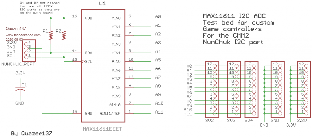 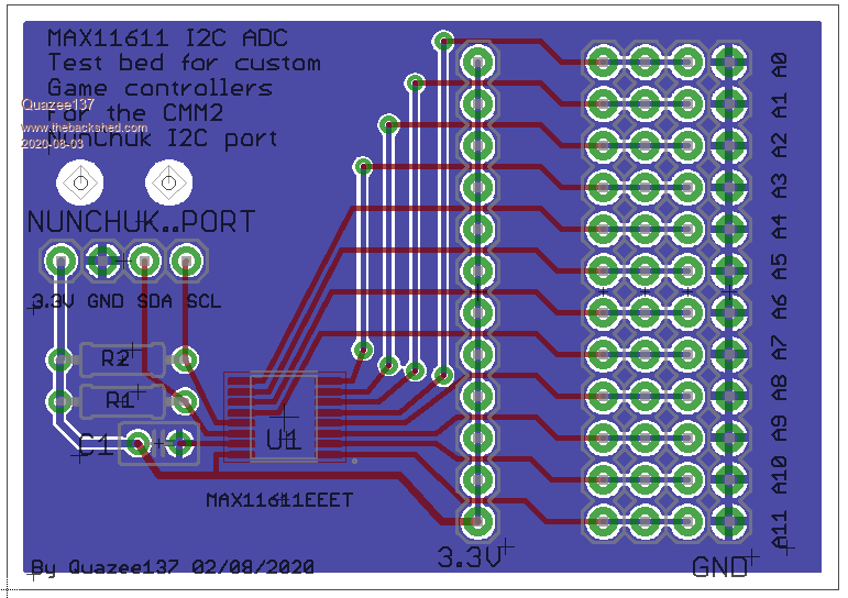 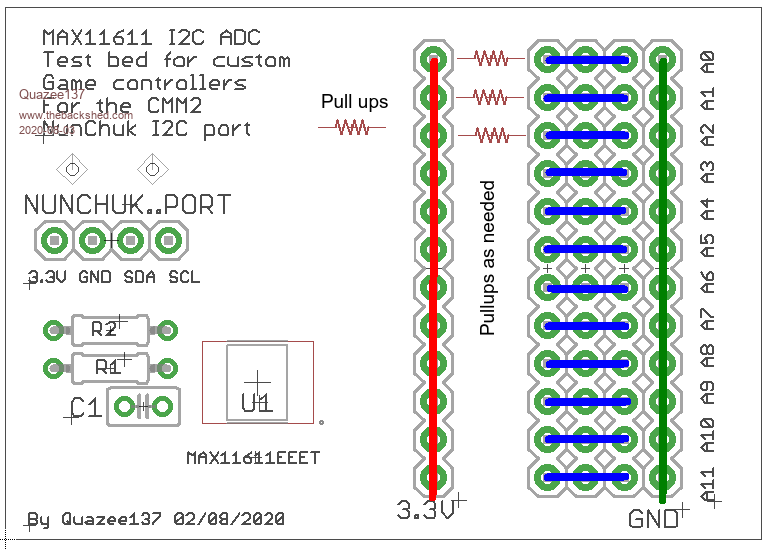 One though is it could be a csub that is timer driven and maps functions to AX pin using a controller.ini file using a standard labeling for the functions i.e Up Down Left Right Joy1 ButtonA ect ..... I am not much of game player other than Minecraft using my xbox one controller on Linux Mint. So this would need to be worked out by TheBackShed's here. If there is interest I will post gerbers. |
||||
| Quazee137 Guru Joined: 07/08/2016 Location: United StatesPosts: 522 |
This is from my MM170 HatStand prototypes. Should make it easier for those Āthat want to play with the 40 pin port. I had moved in March and just unpacked Āthe MM170's and usb with the cad files. Ā 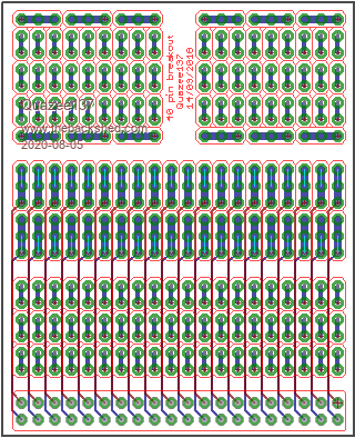 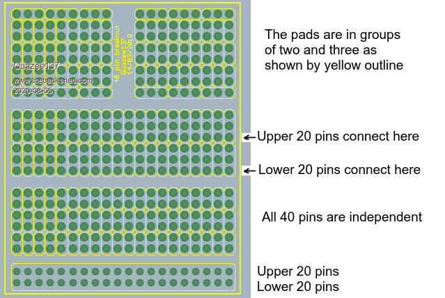 a work sheet 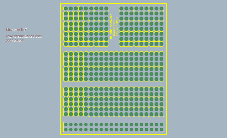 I used theses to interconnect the boards.  40 Pin Breakout.zip have FUN be SAFE Quazee137 Edited 2020-08-05 01:43 by Quazee137 |
||||
| capsikin Guru Joined: 30/06/2020 Location: AustraliaPosts: 341 |
Yeah, maybe we should start a separate thread for the direct pin reading interface. Not sure what we'd call it though. I'm just a bit conflicted about having the pins shared with the paddle/analogue joystick. It seems easier not having to unplug and plug stuff from the 40 pin connector all the time when you're trying out both. While I'm tinkering without proper connectors, it would be handy to leave analogue stuff plugged in while I'm using the digital joystick and vice versa, rather than having to unplug a 40 pin connector or all the separate wires (disclaimer - I haven't actually connected it all up yet) I'm guessing that's part of why vegipete used separate pins for the analogue joysticks' buttons vs the digital joystick's buttons. How would you deal with it if you made an interface box? And if one or two of the pins would sometimes be used for paddles instead of the digital joystick. Connect the pins to two sockets, one for joystick, one for paddle? I don't really mind your proposal personally but I want to minimise obstacles for people to accept it. What about if I go with my last idea but pick a pin instead of leaving it unspecified? Here's my proposal: digital right should be pin 29 for new hardware, software should support that, and may optionally also support pin 40 for backwards compatibility. (I'm thinking it's slightly better to leave part of PWM 1 and part of PWM 2 free, rather than use both the PWM pins, so that's why I'm not using pin 31, but really I just needed to make a decision). Other digital directions are as in the original proposal by matherp. Pins 7,13,15,26 may or may not be used for a second digital joystick in future, that's not part of the proposal. I think that would be enough for me to start writing a controller library (initially for just a single player, digital joystick), and if it gets much use that then tells you the pins to use for your hardware. What do you think? I don't think the ORing is so bad but maybe you're right. It may end up in its own function or sub but it's still good for the code to be clear. |
||||
| Turbo46 Guru Joined: 24/12/2017 Location: AustraliaPosts: 1593 |
Could you please list your proposal for clarity? It's all getting a bit confusing. I'm happy with whatever you choose except pin 40, an accidental reset will confuse an inexperienced user just wanting to play a game. All I'm asking/begging for is a standard pin allocation that will be universally adopted to allow a permanent hardware interface to be used. Bill Keep safe. Live long and prosper. |
||||
