
|
|
Forum Index : Microcontroller and PC projects : CMM2: Recommendations for joystick/game controller I/F standard
| Author | Message | ||||
| capsikin Guru Joined: 30/06/2020 Location: AustraliaPosts: 341 |
I want to support something like the original proposal in my code (i.e. direct pin connections, and using the PIN function) as common convention as lizby suggested. I think that can succeed if the hardware support is there and people want to buy it. I'd rather not make any incompatible changes to it since the discussion went quiet a couple of weeks ago, in case others have already started supporting it. No one's mentioned any communications ports that would be interfered with, except for one of the I2C ports, which is probably okay. I was mainly planning to write code for the digital direction pins and maybe one or two buttons. The original proposal seemed fine for that, and might be enough for atari 9 pin interface (without paddle support). I was a bit unclear on what the analog signals are in the proposals - I might have worked it out now but I want to check. Are analog x,y,z the signals from the same joystick as digital left/right/up/down, or a second joystick for a second player, or a second joystick on the same controller? Are analog x1,y1,x2,y2 the signals for two joysticks, as in a modern controller used by a single player? This is what I initially assumed for vegipete's proposal. But I don't think it's necessary now that people can use the classic controller on the I2C ports. Or are they for 2 joysticks for two players? If so, Turbo46 I like your proposal to support reusing their pins for a second digital joystick for a second player. What would you do about buttons for the second player? For my purposes, I'd be okay with two player games limiting the players to two buttons each, and only single player games allowing 4 buttons. So pin 27 might be single player button C, or player 2 button A. and pin 28 might be single player button D, or player 2 button B. (or correct me if you already had different button assignments in mind/need to discuss it some more. If you wanted to support 2 single button joysticks and 3 I2C ports you'd need to change the button assignment) I don't think it's too late for games to support it. The boulder dash game I've been helping with, for example, only has a small subroutine needing modification, and it can be found be searching for "KEYDOWN". Well, an initialisation section would also be good. But it should be an easy change either for someone already working on the program or a joystick enthusiast who's worked on other games. I think that's probably the case for most games. And while the original author is still around on the forum, they'd probably be willing to allow distributing the change. Developing and paying for the hardware, I don't know so much about. Some people might want to make stuff themselves, some might want to be able to buy it from someone else. I don't know if anyone has plans for hardware to support the analog part of the standard. For digital, it would be cool to have an interface device that would support 1 or 2 atari joysticks (which seem fairly cheap on aliexpress at the moment). And then to have a bundle with the interface and the joysticks. And for people who want to use arcade hardware, it would be cool to have a board that can replace the zerodelay USB interface found in arcade kits. Your interface box idea also sounds cool. One thing I'm not sure about with the Atari joystick interface - were you planning on supporting just 4 directions and a single button? It looks like the standard got more complicated after that but maybe a second button is possible. |
||||
| capsikin Guru Joined: 30/06/2020 Location: AustraliaPosts: 341 |
Seems like it should work but I'm no electronics expert. You'd need some way of checking which wires are which so you can solder them to the right pins. |
||||
| lizby Guru Joined: 17/05/2016 Location: United StatesPosts: 3015 |
Please no soldering to expansion connector pins. At the least use something like BigMik's connectors or ebay connectors or dupont wire flying leads for testing. ~ Edited 2020-07-22 23:03 by lizby PicoMite, Armmite F4, SensorKits, MMBasic Hardware, Games, etc. on fruitoftheshed |
||||
| capsikin Guru Joined: 30/06/2020 Location: AustraliaPosts: 341 |
Right. I didn't mean to the expansion connector pins on the CMM2 itself. I thought there might be a connector you could attach to it that had pins on the back. Like this but with pins on the back. Or like this but fitting the connector properly. Not sure it exists though. How about soldering to the wires in a ribbon cable? Probably a worse idea than the options you linked to. |
||||
| mclout999 Guru Joined: 05/07/2020 Location: United StatesPosts: 430 |
First thing is we are getting WII clasic commands in the RCs and in the new release so using that is the best bet. Second I have used the pcb from a cheep WII classic controller to make a DIY fighting stick. I made it way back in the days and it was trivial to wire up and all the parts from the doner controller where useable, like the cable and connector. That is the best way forward but stock up on crapy WII knockoff controllers. they are so cheap. The next very helpful project would be a small pcb with two WII female ports so we can have a plug-in module for the GPIO connector. I think that this combination would be the most elegent and already integrated solution. It is nice that my old WII fighting stick will just plug in (I later added a USB controler so I can use it with retro gaming on Raspberry PIs and PCs). On having more than 3 controlers you have 10 buttons and a digital DPAD on the clasic controller that can be mapped easily to 2 simple 2 button joystick with a breakout port adapter of your own design. I think that this is where we could establish a standered for attaching 2 controlers to one WII chanale so games could consitanly program for simple controller like SNES. I think they use Shift registers so they would be more difficult to wire. I have always just made the controller part from scrach so one to one wireing to the WII controller pcb was very simple. I look forward to figuring out how to best use the WII functionality for custom controler. |
||||
| Turbo46 Guru Joined: 24/12/2017 Location: AustraliaPosts: 1593 |
Thank you capsikin for your reply. I personally have no experience and little knowledge of analogue joysticks and do not intend to use one unless I really have to. I believe they were used for early PC games and there seem to be plenty available for the Arduino. I don't believe that one has been used on a Maximite to date. All I am really asking for is a recommended standard set of input pins to be used for an Atari type joystick with one or two buttons (but one or two paddles would be nice). Bill Keep safe. Live long and prosper. |
||||
| Turbo46 Guru Joined: 24/12/2017 Location: AustraliaPosts: 1593 |
For additional nunchuks you could use Big Mik's connectors and one or two of these or similar. You could also hack one out of a PCB with a double sided edge connector. Bill Keep safe. Live long and prosper. |
||||
| mclout999 Guru Joined: 05/07/2020 Location: United StatesPosts: 430 |
You could also get a cheep WII extention cable on Amazon 2 for $4.41 10' https://www.amazon.com/gp/product/B01NBP57V1/ref=ppx_yo_dt_b_asin_title_o01_s00?ie=UTF8&psc=1 and then you have 2 male and 2 female connector ports with locking mechinisums and proper orientation protection on the female side at least. �Just cut them to length and wire them up. �Question, if you are connecting them to the GPIO pins do you need any resistors in line for protection? Are there any other precautions to getting them connected? I am thinking of using some trimmed down perfboard and a old IDE cable. The picturs of the units show the lock pin notch of the connector so that would provide some safty for proper pin connections. Thanks. Edited 2020-07-23 01:48 by mclout999 |
||||
vegipete Guru Joined: 29/01/2013 Location: CanadaPosts: 1082 |
I took Bill's connector function diagram and turned it into a CMM2 circuit diagram (hi-res). Hopefully I got everything correct. The only change is the addition of one extra digital input for the fire button of a standard Atari joystick, connected to pin 37. This keeps the digital joystick completely separate from the analog ones and allows the Atari joystick to function with only the end 6 pins (35 to 40) of the connector (plus 3.3V for the pull-ups.) 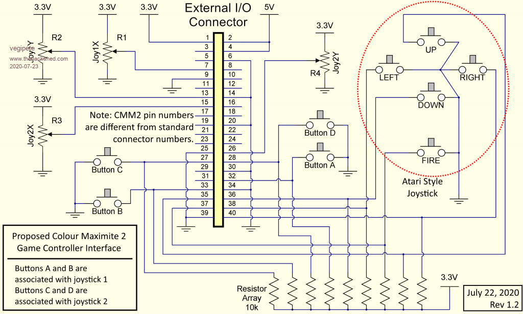 ============ A note about 'classic' joysticks: Classic joysticks, paddles and similar analog input devices, as used for example on Apple][ and IBM-PC computers, are a little bit tricky to use on the Colour Maximite 2. This is because the CMM2 has actual analog to digital converters which expect to digitize an analog voltage. This differs from the classic computers that had no such converters and instead measured the time it took to charge (or discharge) a capacitor through a variable resistor. As a result, the potentiometer is wired as a variable resistor and usually lacks the third wire needed for a voltage divider. At the cost of reduced precision, a suitable resistor pulling the analog input up or down as required should work. Visit Vegipete's *Mite Library for cool programs. |
||||
Quazee137 Guru Joined: 07/08/2016 Location: United StatesPosts: 522 |
Ok here is my ideas for using the numchuck port for all game controllers. 4 ports 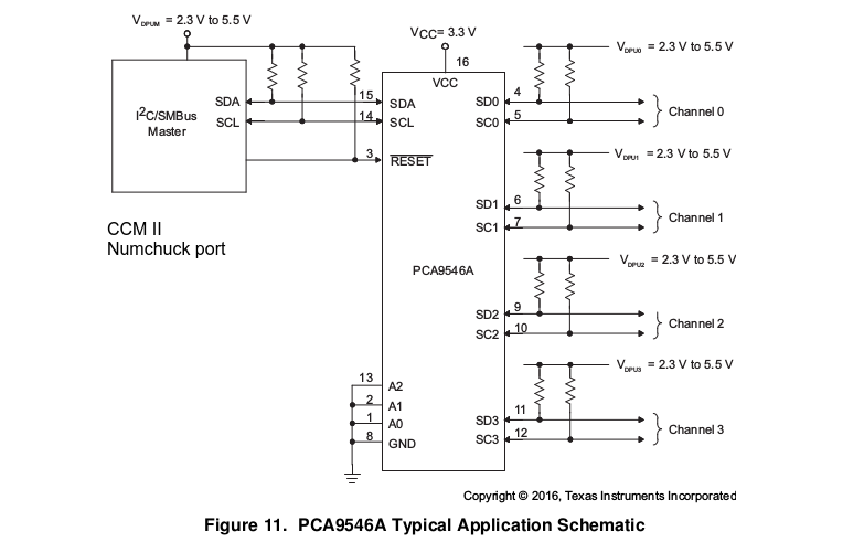 8 ports 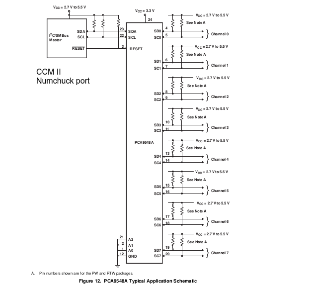 xyz and buttons 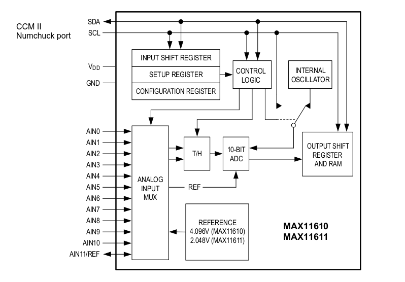 I think you get the ideas now 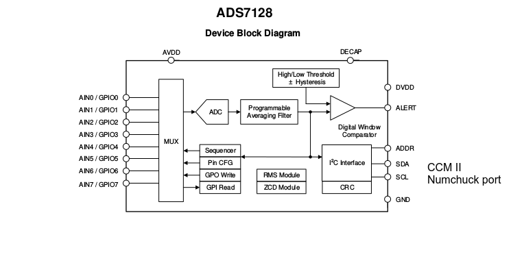 one more 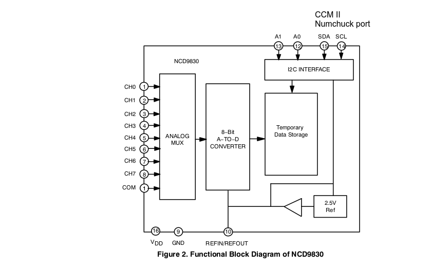 Mouser Digikey Newark ADS7128 $5.95 $5.95 Max11611 $5.10 $5.06 $4.92 NCD9830 $2.91 $2.92 $2.91 PCA9548 $2.36 $2.36 PCA9546 $1.63 $1.89 $0.828 TCA9546A $1.32 $1.32 $1.32 may be a sub library i.e. controller drivers this leaves the back Interface port open for better things. have FUN and be SAFE Quazee137 |
||||
| robert.rozee Guru Joined: 31/12/2012 Location: New ZealandPosts: 2289 |
be aware that using pin 40 is not safe. if it is grounded at startup the CMM2 will erase option settings and (i believe) any user program in flash. cheers, rob :-) |
||||
| capsikin Guru Joined: 30/06/2020 Location: AustraliaPosts: 341 |
Regarding the pull-up resistors for the buttons - do you want these even though the CMM2 has its own pull-up option for pins? For arcade controls people may want to support multiple buttons with the digital joystick. I might go with the original A&B, or A,B,C and D in that case. I think it should be easy enough to support that in one set of code with support for your one button joystick, at least for one player games. |
||||
| capsikin Guru Joined: 30/06/2020 Location: AustraliaPosts: 341 |
How about a board that connects to the I/O connector, and exposes the unmodified side of the I2C inteface on a nunchuk PCB section, so it's easy to add one extra classic controller using the existing software standard, but also uses a multiplexer to support more controllers if the software supports it? Your idea seems good except that it doesn't support the existing standard for adding a second nunchuk/controller. At least so long as the additional software support is easy to write in basic. |
||||
| capsikin Guru Joined: 30/06/2020 Location: AustraliaPosts: 341 |
Okay I don't think I'm using that then. |
||||
| vegipete Guru Joined: 29/01/2013 Location: CanadaPosts: 1082 |
External pull-ups guarantee the pin state even on power up, before optional internal pull-ups can be turned on. Just to make sure. Pin 40 held low on start up is a bigger problem. An Atari joystick held to the right erasing the option settings is less than ideal. I would suggest the start up firmware could be changed to look for a link between pins 40 and 38. If one of the pins tracks the highs AND lows of the other on start up, there is a good chance they are jumpered together - deliberately. Visit Vegipete's *Mite Library for cool programs. |
||||
| Quazee137 Guru Joined: 07/08/2016 Location: United StatesPosts: 522 |
here is an adapter that should be able to work on the CCM2 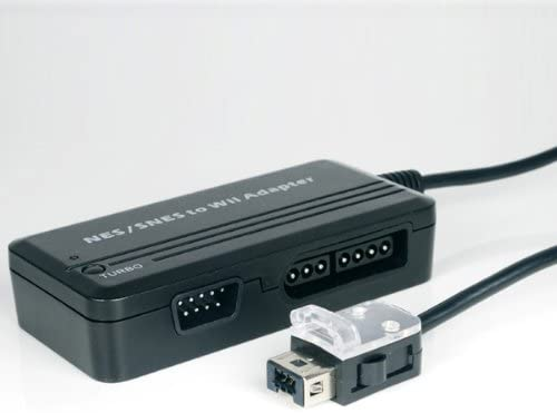 Adapter and some other things to think about insidegadgets I will try to flesh out the earlier ideas I posted here. Just need to finish this current project of 45 units. |
||||
| lizby Guru Joined: 17/05/2016 Location: United StatesPosts: 3015 |
At what point is the grounding of pin 40 checked--is it by some waveshare or on-chip firmware, or is it in MMBasic. If in MMBasic, could there be a prompt at startup asking if the user wants to do the erase, with perhaps a timeout of some period in case part of the problem being corrected by the erasing is lack of connection to console? Perhaps if the erasure is done, a restore image could be written to the SD, with a notice on rebooting after erasure that OPTIONs, etc. could be restored. PicoMite, Armmite F4, SensorKits, MMBasic Hardware, Games, etc. on fruitoftheshed |
||||
TassyJim Guru Joined: 07/08/2011 Location: AustraliaPosts: 5905 |
If the reset occurs, you will have to re-enter your OPTIONs Your program will still be safe on the SDcard The sun will still rise in the morning, World peace will still break out... OK I fibbed on that last one, but having a reset occur is a couple of minutes inconvenience at most, not a disaster. VK7JH MMedit MMBasic Help |
||||
| mclout999 Guru Joined: 05/07/2020 Location: United StatesPosts: 430 |
Check out this addapter. I have no NES of SNES controllers but have a crap load of PS2 and PS3 controllers. I got one of these just to test it when I get my CMM2(Still waiting PATIENTLY!) It could be good. It maps all the PS controls directly to the corresponding on the WII clasic. I have some old favorite PS controllers I would love to use again. https://www.amazon.com/gp/product/B002OJ8S7C/ref=ox_sc_act_title_2?smid=ATVPDKIKX0DER&psc=1 |
||||
| capsikin Guru Joined: 30/06/2020 Location: AustraliaPosts: 341 |
Any interest in picking a different pin for digital right? Maybe pin 37, give up having separate buttons for the digital vs analogue joysticks, and also it's "COM1: DE", I don't know if that's important. I won't do this if you're keeping it for the digital joystick button vegipete, as that would make the code incompatible. Maybe pin 31, which is also the PWM 2B pin (and the PWM 2A pin is already used for digital down) Maybe pin 29, which is also the PWM 1C pin (PWM 1A and 1B aren't used in this Of these, pin 31 is 5 volt tolerant, pins 29 and 37 are not. I don't know if that's important. The original atari joysticks/interface were supposed to have a 5 volts supply. There were some other pin ideas I don't like: Use pin 32 or 33 for digital right, leaving one less joystick button. Use pin 27 or 28 for digital right, leaving one less joystick button, and also you need some detection code to tell whether they are an analogue or digital joystick or a nintendo controller (otherwise you can just run both the code for the nintendo controllers and for the joysticks using separate pins, until you need the 4 buttons for the joysticks). Okay, it could be tolerable. I'd rather avoid it if we can though. One of those might also help, yeah. |
||||
