
|
|
Forum Index : EV's : EV 6
| Author | Message | ||||
Trev Guru Joined: 15/07/2006 Location: AustraliaPosts: 639 |
Progress is being made with the equalizer circuits. Recently been involved with Qld Fire & Rescue, State Road Crash Rescue Challenge. Posted here. Eco Expo 2011 is coming up soon, 5th June. New wheels have been added. 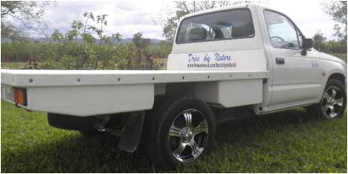
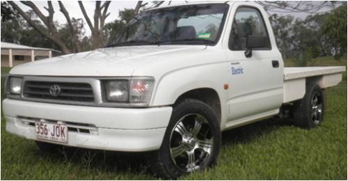
Trev @ drivebynature.com |
||||
| Gizmo Admin Group Joined: 05/06/2004 Location: AustraliaPosts: 5024 |
Flash looking set of mags there Trev  The best time to plant a tree was twenty years ago, the second best time is right now. JAQ |
||||
| Trev Guru Joined: 15/07/2006 Location: AustraliaPosts: 639 |
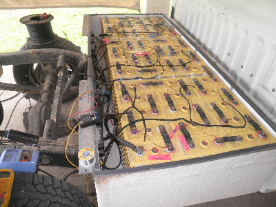
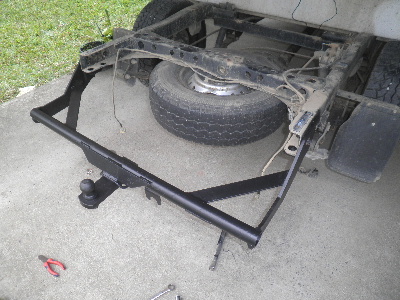
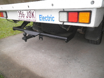
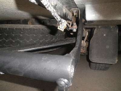
Some more changes with the EV Hilux. The test samples of the equalizer circuits have arrived and so needed to work on re mounting the 2 Zivan chargers. They used to be under the bonnet, but I had trouble with one (the first and so was the oldest). It eventually stopped working due to water ingress and dust. I bought a new one. The 2 Zivan chargers are now mounted behind the drivers seat. No more water and dust. The Zivan charger has an open/closed circuit in the end (facing up in the picture below) that can be used to switch on the equalizer cicuits, when the Zivan charger reaches trickle phase. This is now connected as well. I just need to get a different relay to make it work. These equalizer circuits have been improved. They have an output of 4 amps, but also are physically bigger as well. These 2 have been tested and worked well. I have ordered a commercial quantity. Also have fitted the original towbar back on. First cleaned and painted. With this towbar fitting, I had to cut the fibreglass back to allow room where the towbar bolts on. 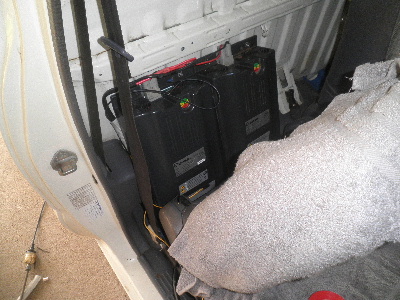 
Trev @ drivebynature.com |
||||
| Trev Guru Joined: 15/07/2006 Location: AustraliaPosts: 639 |
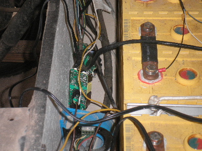
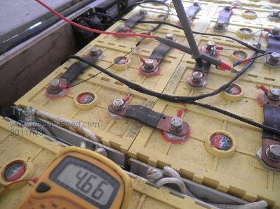
Some more to add about the DC/DC equalizer system testing. These samples I have sealed them up and mounted in the battery box. Tested well for a while but then they stopped working. I put the multi meter in the output wire to see how much current, if any, was flowing. They worked well, too well, more amps then they are supposed to put out. The pic below shows 4.66 amps. I had seen as high as 5.8 amps, at one stage. But then, take the multi meter out of the circuit output wire and they did not charge. It was found that they only worked with a small resistance. So I calculated the resistance provided by the multi meter - 0.047 ohm or so. The smallest resistance I could find was 0.1 ohm. It worked, but cut the current back too far, back to 2.4 amps. I have requested that the manufacturer add a small resister to the output of the circuits. This is charging the low volt cells from the higher volt cells.(far better than the 0.6-0.8 amps that some burn off systems have from other manufacturers). 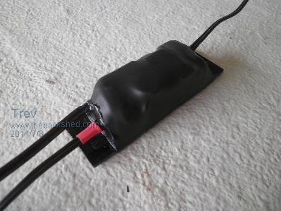 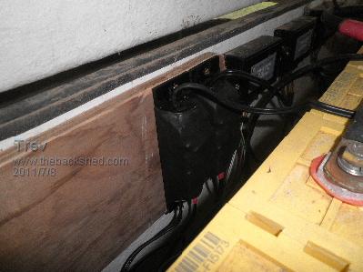
Trev @ drivebynature.com |
||||
| Tinker Guru Joined: 07/11/2007 Location: AustraliaPosts: 1904 |
Trev, 0.047 Ohm could be easily provided by a short length of wire. A little experimentation should give you the right size and length. If you prefer to use a resistor use 2 x 0.1 ohm in parallel, giving you 0.05 Ohm which is very close to your target. Klaus |
||||
mac46 Guru Joined: 07/02/2008 Location: United StatesPosts: 412 |
Hello Trev, Many people may consider this a trivial thing, however this is "Huge", "Huge"... You'r doing things others have'nt done or even contemplated, keep up the exellant work. Simply genious. You'r words and posts are deffinately worth waiting for. ...Mac46 I'm just a farmer |
||||
| Trev Guru Joined: 15/07/2006 Location: AustraliaPosts: 639 |
Yeh Tinker, I tried that with higher value resisters and got lower, but not enough. When I doubled the 0.1 ohm resisters it didn't make any difference when I measured it. Don't know why. It should have been half the resistance. Thanks for the compliment Mac. My electric learning curve is a long way behind many others. In fact there are a lot of fore front runners on this forum. And those that aren't, learn something new anyhow. Really, thanks to Glenn, we all can learn from each other. Trev @ drivebynature.com |
||||
| Trev Guru Joined: 15/07/2006 Location: AustraliaPosts: 639 |
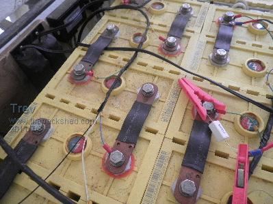
Equalizing stuff up. I have 1 cell in particular (cell 23) requiring a top up every week end to maintain comfortably the range I need. I have these 2 equalizer samples on cell 23 (centre of the pack, & always the hottest) and cell 5 (which isn�t really bad). Cell 5 did not have the resister and therefore was not charging (no problem anyway), but cell 23 did have the resister. Cell 23 was low so I switched it on, without the main charger on, holding pack voltage, and thought I would come back later and switch it off before it got higher than the other cells. I forgot. That in itself is not a problem because the equalizer charger will only go to 3.75v. The problem occurred the next morning after I had charged the pack with main charger. Cell 23 was higher than the others and so became over charged, by 0.7v. As pictured. This would not happen if a complete system was in place. These are samples in test. The complete system requires all cells have their own equalizer charger and they are only switched on with main pack charger holding full pack voltage. As a result I noted a huge internal resistance in cell 23. With a full pack voltage, at 300A, temperature at 18C the terminal voltage drops to 1.7v. Remove the load and terminal voltage comes back to 3.3v. As the cells warm up, the terminal voltage under load drop is less, but even at 40-50C the terminal voltage of cell 23 drops below 2.5v with load. I see the same pattern when charging. The load of the charger pushes the terminal voltage of cell 23 higher, but as the charger cuts back at the end of charge, the terminal voltage comes back to normal. I also note that heat generation is now higher in cell 23 than it used to be. On a positive note, I have not noticed any drop in capacity in cell 23. 
Trev @ drivebynature.com |
||||
| Tinker Guru Joined: 07/11/2007 Location: AustraliaPosts: 1904 |
Trev, placing 2 x 0.1 Ohm resistors in parallel gives you close to 0.05 Ohm. If your measurement gadget does not say that then I would doubt the gadget, FYI, it requires a *very* good connection at such low Ohm readings *and* the measuring current is much higher than the standard multi meter can supply. IOW, you need a special low Ohm meter, I believe there is a kit for this available from the kit suppliers. Klaus |
||||
| VK4AYQ Guru Joined: 02/12/2009 Location: AustraliaPosts: 2539 |
Hi Trev I use nichrome wire for low resistance resistor, I know it is difficult to measure but if you put a bit in and shorten it till you get the result you want, it works but a bit low tech, after you calibrate one piece then you can get many from a piece of wire. Make a pin jig to wrap the ends around for termination. Available at Jaycar All the best Bob PS: Jaycar had a low ohms kit available a few years ago might be a good thing if you are playing with low ohms applications, the other way is to measure a meter of the wire to bet a base line resistance and then use measurement to get a close to it resistor. Foolin Around |
||||
| Trev Guru Joined: 15/07/2006 Location: AustraliaPosts: 639 |
The EV Hilux has now passed the 50,000km mark with the LFP Thundersky (now called Winston Batteries) battery pack. They were fitted with speedo reading 350153 and now is 400231. That is 50,078km. Range check, did 91km using 19.5kWh, driving mostly at 100km/hr. Some capacity drop from last range check, but a lot better than I thought it would be.These LFP batteries were fitted in August 2008. It is now August 2011. 3 years. My guestimation is something like 800 cycles at high currents & very deep discharges. Temperature is often around 40 to 50C, at the centre of the pack (cell 23). The edges of the pack are 5-10C lower. Today with range test the centre reached 60C and the edges are at 43-46C. These batteries still do not have any automatic equalizing system on them. Balance every weekend, basically I just keep the pack at full voltage and switch on the 2 x single cell DC-DC converter chargers shown in previous post. Once a month I do a rough manual balance with some of the other cells. As said cell 23 is the one that most of the fuss is about, but as just proven, still has the capacity, so is still worth the effort to keep topping it up. Really, these batteries have taken a flogging (& still going) compared to what lead acid would give. I am impressed to say the least. They will be in the Hilux for some time yet. 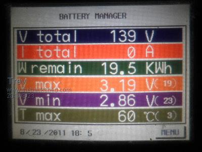 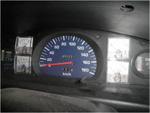
Trev @ drivebynature.com |
||||
| Trev Guru Joined: 15/07/2006 Location: AustraliaPosts: 639 |
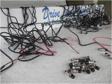
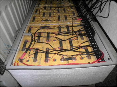
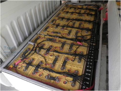
Time to catch up a bit It has been a long time since I said I had ordered a commercial quantity of single cell chargers. Well, because we discovered that they stopped charging after a while, and needed a resister in the output, we asked the manufacturer to add the resistance. They refused. I cancelled the order and took close on 6 months to get my money back. Thankfully they did eventually refund it. I was not keen on spending the time to add the resistance and have a product with reduced output current as a result. I still had to do the packaging. With the original test circuits, I used heat shrink over the circuit and base board, with potting in both ends to seal it up from dirt and water. All this hand work would make them too expensive for sale. A new supplier and a new product were found for single cell charging. The output of these chargers is 3.7vdc. Input is pack voltage, 167vdc. 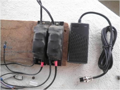
I set about installing them. All the input wires were connected in parallel. The input was to be switched through a solid state relay from the Zivan NG3 charger. The relay fried itself before I even connected it up properly. I tested the function by holding the coil wire (12v) and the output just went closed circuit, but would not reopen. So the test was conducted by manually switching the 3.7v chargers on. When you look at all the wire it looks a bit scary. But just work on one at a time and it�s all easy connecting. It doesn�t look so bad when all cable tied neatly. 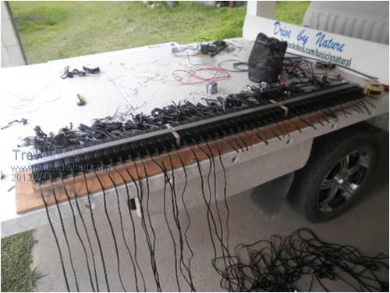 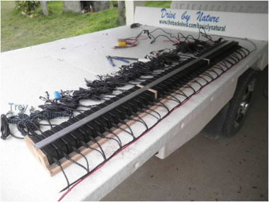
Test 1 The Zivan charger was to charge to it normal voltage of 167vdc and holding battery pack voltage, the 3.7v chargers are switched on. The high volt cells do not get charged, because they are higher than the 3.7v output of the charger, but drain off because the chargers on the low volt cells are taking power to charge. The idea was to get them all to be of similar voltage. The pack at 167v, the highest cell, no.6 at 4.07v and the lowest cell, no. 35 at 3.58v. Only the highest and lowest cell was monitored until it was evident that it was not working. Note, cell voltage come down but then go up. Cell voltage go up but then come down. Output of the chargers were not stable and fixed. Mostly however the cells remained fairly close together in voltage, but not reliable with a number of cells going haywire. 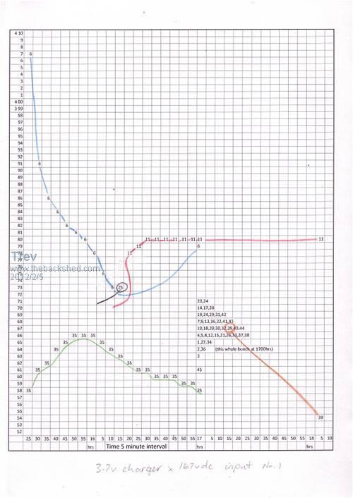
Edit: attempting to see what happens with resizing pictures. Pictures need to be 501 pixels wide or more to get the watermark. Pictures above 500 pixels wide will auto resize to 500 pixels wide. Pictures need to be 390 pixels wide to fit 2 side by side with a space between them. No space to picture underneath. To get the water mark on pictures smaller than 501 pixels, upload as normal. Copy the picture, resize to required size and edit post, re-uploading picture with watermark. Or put your own watermark on first. I used to have all my posts with pictures side by side. New software changes the rules. Scanned the graph with different dpi trying to get it bigger, but makes no difference to view size when uploaded. To view bigger, on your web brouser, click tools, click zoom. Trev @ drivebynature.com |
||||
| Trev Guru Joined: 15/07/2006 Location: AustraliaPosts: 639 |
Test 2 All cells were monitored. I took hundreds of photos of my Battery Monitoring Screen. Then many hours going through the screen shots to trace the behaviour of the cells. A random sample has been added to the graph, including the highest and lowest cells of the pack. Cell 21 mucked me up. The charger output open circuit was too high and so the test was abandoned after 45 minutes when cell 21 became 4.22v. The results seemed to be a bit more like the expected. High volt cells coming down and low volt cells going up. But take a close look at the cells in the random sample in the middle. The voltage they start from is exactly the same voltage they finish on, no real benefit. So with a pack voltage of 167vdc, high cell,6 started at 4.05v and low cell, 13 at 3.50v and finishing up at high, cell 25 at 3.73v an low cell, 36 at 3.56v. That's 0.17v difference. The chargers are all measured to be close on 3.7v, so the results are not as they should be. 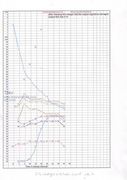
Trev @ drivebynature.com |
||||
| Trev Guru Joined: 15/07/2006 Location: AustraliaPosts: 639 |
Test 3 The Zivan charger output was wound back to 155vdc. The same 3.7v chargers were run with a 240vac input. The results are as expected. Cell 11 and 6 showed up as the high cells like in other tests. Cell 36 was obviously quite bit lower in state of charge than the others. Most cells were fairly close in voltage after 1 hour. But it was around 3.5 hrs to get them all to be similar voltage. I ran this setup for a while, charging over night with the Zivan to 155v and then in the morning I switched on the 3.7v chargers. It was usually around 1/2 an hour to have them all to be within the highest of 3.79v an lowest of 3.70v. This is by far the closest I have ever had the cells in my battery pack. (To manual balance 45 cells with 4 small 0.3A x 3.65v chargers and 2 auto lights takes 3 days to change the pack very little). The biggest problem of this balance option (single cell charging) is the connection of so many wires, input and output, but for a balanced pack in 1/2 an hour every morning is brilliant. 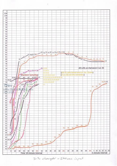
Trev @ drivebynature.com |
||||
| Trev Guru Joined: 15/07/2006 Location: AustraliaPosts: 639 |
Here is the pictures of the BMonitorS main screen at the start and finished of the graph in the previous post. 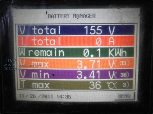

Every morning, within 1/2 an hr, finished at the same, high 3.79v and low at 3.70v. A difference of just 0.09v. Trev @ drivebynature.com |
||||
| Tinker Guru Joined: 07/11/2007 Location: AustraliaPosts: 1904 |
Hi Trev, This idea of single cell charging has me intrigued. I'm sure you have your reasons for doing it that way and I would be interested to hear them. I was just trolling through the ev power website to read up about LiFePO4 batteries and their suitability for my house battery bank replacement. They seem to use one large charger, individual tiny BMS shunt controllers on each cell and one master BMS unit. So, is your method a better way to charge these batteries? Klaus |
||||
| Trev Guru Joined: 15/07/2006 Location: AustraliaPosts: 639 |
Tinker, I have sold quite few of these Winston Lithium battery pack for wind/solar systems. Lots of them into the camper/caravan market. In my opinion, these batteries are far superior to lead acid batteries. Cost is not much different. I will add more over the next few days about balancing. Trev @ drivebynature.com |
||||
| Trev Guru Joined: 15/07/2006 Location: AustraliaPosts: 639 |
I believe this balancing issue is really related to a few operational characteristics. They don�t stray too much in voltage if�.. 1) there is a low cell count in the series string (I have 45 cells, less is less cell variation, although the LYP seem to be more consistent in quality anyway. I have LFP) 2) used between 3.0v and 3.6v (I charged repeatedly to 4.2v when they were new, I don�t anymore. I have drained a few of them below 2.5v too, not good. Charged to 4.6v is very bad) 3) all cells kept at an even temperature (the middle of my pack is always much hotter than the edges. This is where I first noticed cell problems) 4) low charge & discharge currents (I am frequently discharging with 200 to 400amps, puts much more strain on them) I have 4 cells x 90ah LFP in the Hilux EV as the 12v pack and has not been balanced since I tested the first Relativities Active Balancing circuits from Gordon. I have no problem with them. I have a 12v block of 200ah LYP I use on my camper trailer. They have never been balanced. Currently I have this 200ah block on my house wind/solar in series with 3 x 12v 200ah lead acid batteries. Initially, every day I check them and they are within reason. Now I check them every week or 2 and the voltage difference is still reasonable. The cells do not have to be exactly the same to operate. The key is not to have any cell go above 3.6v and no cell below 3.0v. I have said it before, but worth repeating, in a worst case senario, if one cell was at 3.6v and one cell at 3.0v then you can't charge with out damage and you can't discharge without damage. There is no problem if a cell is at 3.6v and a cell is at 3.5v. For peace of mind, I believe Relativities Active Balancing is the answer to keeping the voltages all balanced all the time. Gordon has tested the Relativities on his Wind and Solar setup for the past, must be near 3 years, and have never missed a beat. They have been cycled to 80-90% DOD every day. His recent capacity test showed no loss of capacity in the LYP cells whatsoever. We are still working on Relativities to become a commercial product. The issue we had seen originally with Relativitities is that it takes a long time to transfer power from a high volt cell in one end of a long string to a low cell in the other end. I bought some 14.8v chargers with the idea that I could use them to assist in transfering power quicker in a long series string (not tested yet). Gordon is currently working on a set of Relativities circuits to test on the Hilux EV based on his latest design. Trev @ drivebynature.com |
||||
yahoo2 Guru Joined: 05/04/2011 Location: AustraliaPosts: 1166 |
Trev, I have been reading posts on various forums about Lithium Iron poly batteries for a number of years. I look at some of the claims and stories with a mixture of fascination, enthusiasm, disbelief, confusion and sometimes a bit of horror as well. It is hard for me to get a good idea how a renewable energy LiFePo battery bank could be set up and managed, so much of the info I read I simply don't trust or understand well enough to say to myself " that guy is an idiot or has some axe to grind!" I would like to ask a few questions but I don't want to stuff up your excellent thread on EV's. Would you and Gordon be willing toss a few ideas around if we started a topic focused on these batteries used as a off-grid or backup power solution? regards yahoo I'm confused, no wait... maybe I'm not... |
||||
| Trev Guru Joined: 15/07/2006 Location: AustraliaPosts: 639 |
Yahoo2, no problem, you can start a thread if you like. Cell 13 was cell 23. Position 23 is the centre of pack and is always the hottest. This cell showed signs of greater internal resistance. Then appeared to charge higher and discharge lower than the others. I shifted it (the whole 5 cell block) to position 13 so that it would be able to cool better. As stated in a previous post, I had over charged it by quite a bit. This over charging created a masive internal resistance. I continued using it but under normal discharging (driving) it always sagged to 1.0 -1.5v. As soon as discharge stopped it sat on 3.0v +. It was not empty. It still drove me round trip of 75km each day for a good while. It has now been removed from the series string. The last couple of trips was driven with it sagged to 0.0v when pulling around 100-150A. It showed normal voltage 3.0v, with no discharge. Then you can see what happens with 15A charge. The resistance in the cell pushes the voltage up. I believe this is only tension, not really what is in the cell. Terminal voltage only if you like.  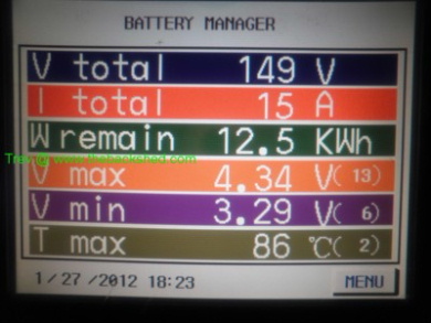
Then the next day I run the charger for a little while. Pictures are charging at 15A and 31A. You can see it doesn't need much current to give the voltage rise.  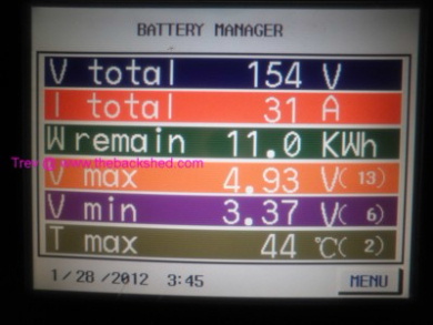
I let it charge with both chargers (31A) and near the end of charge the voltage rises quite high. (Originally I had the chargers set to 167v, but currently is set to 156v). 1 charger is set slightly lower voltage to the other and so 3A still coming from the 2nd charger. I disconnected the 2nd charger to show 15A.  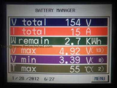
I switched off the charger and then switched it back on. See cell 13. 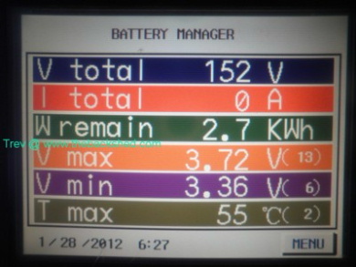 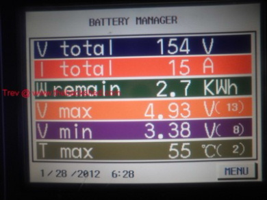
Seperated battery block, shifted cell 13 to the end and then put back together. Clamps hold it together to get the srews back in the stainless stell bands. Back in the Hilux, cell 13 now is cell 45. It just takes up space. It is not connected in the series string. I had to put it at the end so the Battery Monitoring Screen still reads corectly. 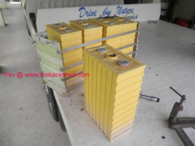 
I still have been driving my usual round trip of 75km with some capacity spare. The loss of one cell is not noticeable. Trev @ drivebynature.com |
||||
