
|
|
Forum Index : Electronics : a new way to balance lithium ion battery
| Page 1 of 11 |
|||||
| Author | Message | ||||
| Tinker Guru Joined: 07/11/2007 Location: AustraliaPosts: 1904 |
Recently a 200Ah LYP battery was added to my house battery bank. These batteries are unfortunately still about 2.5 times dearer than a bog standard LA deep cycle battery of similar Ah & voltage rating. But the lithium battery offers a much longer service life provided a decent charge management system is in place. For that requirement, overcharging is controlled by the MPPT controller that feeds the battery bank from the solar panels. Over discharge is handled with a low voltage disconnect that cuts off the lithium bank from the rest of the battery bank once it drops to 24V. Unfortunately my inverters have a much lower cutout setting so the extra lithium protection was installed. That leaves the task of cell balancing to ensure each of the 8 lithium cells (24V bank) are always kept at an equal charge potential. Usually that is done with a shunt type bypass connected straight across each cell's terminals. While this works it seems to me there should be a smarter way of doing this - the shunt bypass only starts working once the cell has charged to its upper limit and then the shunt dissipates any additional charge as heat. One ex forum member is developing a more clever way of LiPo cell balancing (see the EV section) but its not yet available for sale and I wanted one  . .
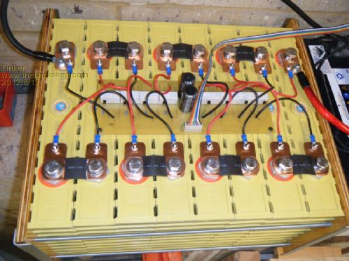
So I decided to come up with my own version, one that does all what apparently the "Relativities" unit was doing. Balancing would ideally commence as soon as any charge current flows to the LiPo battery cells, in other words, not being dependent on their state of charge. This sounds quite a task but I found a way of doing that which is remarkably easy. So easy in fact that I wonder why apparently nobody else (as seen on a quick Google search) has thought of it. I'll post a picture of it below, the keen observer amongst you should be able to figure out how it works, its that simple. No prizes for the right guess unfortunately but the nice feeling to know my secret  . .
The next picture is the whole set up, the ribbon cable leads to a little black control box that's mounted on my super capacitor bank frame. 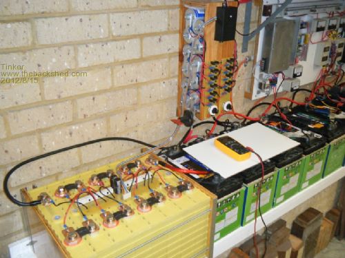
That's it. Further descriptions after I get a right guess. Klaus |
||||
norcold Guru Joined: 06/02/2011 Location: AustraliaPosts: 670 |
I`m waiting with baited breath for that guess. Being a paint by numbers electronic user (abuser!!!) I`ll have to go with magic  or ask the audience. or ask the audience.We come from the land downunder. Vic |
||||
Downwind Guru Joined: 09/09/2009 Location: AustraliaPosts: 2333 |
A close up photo of components would help, as all i can see is 2 big electro caps and a nest of wire, what are the white things? caps, resistors, lego blocks, ....?? Worked it out .... its black box magic. Knowing Tinker it more than likely uses a comparator and relay. Well i give up.......this game is no fun! Sometimes it just works |
||||
| Warpspeed Guru Joined: 09/08/2007 Location: AustraliaPosts: 4406 |
Ah yes, this is a very good idea, but the relay contacts are going to lead a very difficult and probably short life from the high inrush current spike. A low value resistor placed in series with the electrolytics would reduce the small "splat" when the contacts close, and introduce very little extra loss. Now let me guess.... The eight relays are driven in mixed sequence to connect the electrolytics alternatively across every cell. The electrolytic charges from the high cells, and discharges into the low cells thus equalizing all the voltages over time. A really nice way to do this would be with a long sequence random number generator where any three bits generate numbers from 0 to 7 in a very long random sequence. These are not difficult to build. http://en.wikipedia.org/wiki/Linear_feedback_shift_register Then use a three input, eight output decoder chip to select and operate each of the eight relays in completely random order, so only one relay operates at a time. Cheers, ĀTony. |
||||
powerednut Senior Member Joined: 09/12/2009 Location: AustraliaPosts: 221 |
Yeah, it does look like a comparator (the little black spec in front of the white box) and relay combination (white box). I'm guessing its similair to a ghurd controller for each battery, with state/control being handled via the relay or perhaps an optocoupler. |
||||
yahoo2 Guru Joined: 05/04/2011 Location: AustraliaPosts: 1166 |
Or you could go with the "She'll sort er self out, mate" theory spotted this on a info page about upgrading from 24 volt Lithium Ion to Lithium Iron phosphate. 
2. Large overcharge tolerance and safer performance A LiCoO2 battery has a very narrow overcharge tolerance, about 0.1V over 4.2V of charging voltage plateau and upper limit of charge voltage. Continuous charging over 4.3V would either damage the battery performance, such as cycle life, or result in firing and explosion. A LiFePO4 battery has a much wider overcharge tolerance of about 0.7V from its charging voltage plateau 3.4V. Exothermic heat of chemical reaction with electrolyte measured by DSC after overcharge is only 90J/g for LiFePO4 verse 1600J/g for LiCoO2 . The more is the exothermic heat, the larger energy heating up the battery in its abusive condition, the more chance of fire or explosion. A LiFePO4 battery would be overcharged up to 30V without protection circuit board. It is suitable for large capacity and high power applications. From viewpoint of large overcharge tolerance and safety performance, a LiFePO4 battery is similar to lead-acid battery. 3. Self balance Like lead-acid batteries a number of LiFePO4 cells in a battery pack in series connection would balance each other during charging process, due to large overcharge tolerance. This self balance character can allow 10% difference between cells for both voltage and capacity inconsistency. See, why do we bother, just plug em in and let it rip.  
In their defence if they fitted a balancing charging system and doubled the battery life they would price themselves out of that market, but it still bothers me to see this drivel published. They have not said anything that is not technically correct, but they fail to mention the compromises this charging method has. I'm confused, no wait... maybe I'm not... |
||||
| paceman Guru Joined: 07/10/2011 Location: AustraliaPosts: 1326 |
Yes, and what happens when one of the cells dies and won't hold charge above some low voltage. |
||||
| Georgen Guru Joined: 13/09/2011 Location: AustraliaPosts: 462 |
Is it possible to install some balancing device despite of such a blaze approach by manufacturers? George |
||||
| yahoo2 Guru Joined: 05/04/2011 Location: AustraliaPosts: 1166 |
I doubt it would be worth the effort, its marketed as a sealed unit, bit like a laptop or cordless drill battery. There are a few 12v ,24v and 36 volt packs that have "internal voltage balance" on the brochure, probably a better bet to start with one of these and a quality charger. I expect they will start to pop up everywhere before long, I see they have started to appear as the next big thing to replace standard motorbike batteries. I'm confused, no wait... maybe I'm not... |
||||
| Tinker Guru Joined: 07/11/2007 Location: AustraliaPosts: 1904 |
Congratulations Warpspeed  , I'm glad I'm not the only smart cookie on this forum , I'm glad I'm not the only smart cookie on this forum  . .
But your guess is lacking the correct detail so I'll explain: The "little white boxes" are relays. They have 7A rated contacts (*must* be DPNO) and I'm using 24V coils for their much higher coil resistance. The "comparators"  are just NPN transistors to drive the relay coils. Sorry Downwind are just NPN transistors to drive the relay coils. Sorry Downwind
The "electrolytics" are actually 100F super capacitors, I'm using 2 in series to get a 5.4V rating. Sorry, no "mixed sequence" or random number generator in the black box, much simpler electronics used. It contains, wait for it... A clock (555) that outputs pulses with an 'on' time much longer than the 'off' time. A sequencer, configurable in 4 steps (4 cell bank) 8 steps ( my bank) or 16 steps (for 48V systems). The sequencer drives the relays in sequence, only one relay at a time is turned 'ON' and then the sequence repeats. A 8 step cycle takes about 20 seconds to repeat itself. That's easily changed by altering the clock timing capacitor. A little reed relay with 2 zeners in series to its coil. This relay is powered by the solar panel output directly. It turns on when the panel voltage is greater than 28V, which is the level at which my MPPT starts putting out charging current. The relay turns the power to the clock & sequencer on & off. Clock & sequencer off means the circuit goes to sleep for the night and wakes up once the batteries are accepting charge again. The little black box runs on 12V, taken from the lithium bank. It's been in use only for a short time and so far so good - no sign of busted relay contacts. The super caps were carefully pre charged to the cell voltage before connecting it all up. Measuring each cell voltage at sunset today showed a difference of only 5mV between the highest & lowest. I doubt the relay contacts have a hard life if such small differences is what they see in service. I can easily fit "a small resistance" in series with the relay coils but they may already have one in the form of the fusible wire jumpers I fitted to the board. BTW, anybody planning to duplicate that contraption, the super caps *must* be the high current type, not the memory backup type. I got all my parts from Altronics. Now you know what I was up to lately Klaus |
||||
| norcold Guru Joined: 06/02/2011 Location: AustraliaPosts: 670 |
Still French to me, you haven`t reinvented the wheel? Tinker. Have you seen the LiPol chargers used by rc`ers the cells have a wire from each cell plus a common these along with the main + & - connect up to the charger. Balancing is down whilst charging or using a seperate balancing cycle. Chargers are cheap as chips and batteries are flogged from fully charged state to 20% or less in 5 minutes, often having a current draw of 60-100+ amps for brief times. Cycled as such for 100`s even 1000`s of times. Batteries come in all sizes and voltages with some single charger handling from 2 cells to 10 cells, coming in 50,100,500 etc watt versions. We come from the land downunder. Vic |
||||
| Warpspeed Guru Joined: 09/08/2007 Location: AustraliaPosts: 4406 |
It's a great idea Klaus, simple low cost and effective. I still feel the relay contacts are likely to pit and burn from the initial current inrush over a long period. It needs "something" with a timed delay, to quickly ramp up the current AFTER each relay contact has firmly closed. Just one simple circuit in series with the ultracap. A single MOSFET would do it, they conduct in either direction when on, and unless the cell to cell voltage difference rises to greater than 0.6 volts, (which it never should) the internal source drain diode will not effect operation. While operating the relays in a fixed sequence will certainly work, a completely random sequence should be more effective with a very large string of cells, and it isn't that difficult to do. Cheers, ĀTony. |
||||
| powerednut Senior Member Joined: 09/12/2009 Location: AustraliaPosts: 221 |
nice work - thanks for providing the detail Tinker, I love learning new tricks (to me anyway) like this. |
||||
| Tinker Guru Joined: 07/11/2007 Location: AustraliaPosts: 1904 |
Yes Vic, I looked at these. But I doubt that RC'ers use 200Ah battery banks that weigh about 70 kg .
I prefer my method of balancing, for a house battery bank one aims for several thousands of charge cycles and discharges never below 50%. Klaus |
||||
| Tinker Guru Joined: 07/11/2007 Location: AustraliaPosts: 1904 |
Thanks for the tips Tony, I did consider Mosfets but as I'm not very familiar with these I opted for a simpler solution. Since the battery cells equalised so well after just one day I have now put the circuit to sleep over the weekend and will measure the cell voltages without equalising tomorrow & Sunday. It may be that this gadget needs to run just for one day each week so the relays would last quite long. The contacts have a quoted electrical life of 100,000 operations at full current rating. Unfortunately I cant think of an easy way to find out just how much current is involved but I suspect its quite small. I can't see how random sequences are more effective than a fixed sequence, even for a string of 32 cells. Longer strings will be no longer cost effective with this method, the relays are quite expensive as are the super caps of which more might be required to keep the lead length (to the cell terminals) short. Anyway, if you have time post a circuit of your suggested ramp up, I am interested to experiment with that idea. Klaus |
||||
| norcold Guru Joined: 06/02/2011 Location: AustraliaPosts: 670 |
Tinker, Your dead right rcer`s don`t have batteries that weigh 70kg(although some are getting there), but they have embraced LiPo`s in a big way, of course on a smaller scale. I have a little over 1000kg of LA batteries in my off-grid set up but only a couple of kilos of lipo`s in my rcer setups thus understand where you are coming from. From those experiences I feel for long life LA`s should not be taken below much below 70% capacity whereas Lipo are going down to 20% and even further, that and other features is what makes lipo`s so attractive. Can afford tp play with $15 batteries but not $15000 batteries. Commercially manufacturers have taken on board the demand of rcer`s,re. the multitude of chargers, batteries right down to the explosion proof charging envelopes. Hopefully demand will drive this on a bigger scale and solve off griders battery problem. Tis exciting times. We come from the land downunder. Vic |
||||
| Warpspeed Guru Joined: 09/08/2007 Location: AustraliaPosts: 4406 |
Klaus, You only need one MOSFET to control the instantaneous peak current surge in and out of the Ultracap, immediately after the contacts have closed. All the individual cell switching would still done by multiple relays, exactly as you have already done. I don't have a lot of free time right now to think this right through, but I will definitely come up with a circuit suggestion. When you have fixed sequential relay operation of say 24 cells (or more) the voltage on cell number six, is then switched across cell number seven, and the voltage of cell number seven is switched across cell number eight, and so on, right up through the whole chain. The voltage on cell twenty four is then switched across cell number one, and around it goes again. Any voltage differences transfers charge to the next adjacent cell in the switching sequence, but only in the direction of switching, and always in the same exact order. It might take quite some time for charge to transfer from say cell fifteen to cell six, because it would have to first transfer from 15, to cell 16, to 17, 18, 19, 20, 21, 22, 23, 24, 1, 2, 3, 4, 5, 6. Now a totally pseudo random switching pattern will connect every cell to every other cell directly at some point in a long repeating pseudo random sequence. This would allow charge to re distribute more evenly around the whole battery much faster. If one cell is really sick, say cell number four, number four will repetitively pull down cell number five in a fixed sequential switching pattern. With a pseudo random pattern, cell number four would then be connected to EVERY other cell in the bank evenly, and should be able to recover much faster without placing a heavy burden on only the next adjacent cell. Cheers, ĀTony. |
||||
| norcold Guru Joined: 06/02/2011 Location: AustraliaPosts: 670 |
2012-08-17_232431_Balancer.pdf This balancer will set you back $25 does 8 cells at only 300ma/cell balancing, can be run as the cells are charged from another source. Am I guessing here, but won`t 300ma/cell max balancing current(continuos)be enough for a 5AH or 500AH battery? I know it takes the fun out of designing and building but can it achieve the objective? We come from the land downunder. Vic |
||||
| yahoo2 Guru Joined: 05/04/2011 Location: AustraliaPosts: 1166 |
Yep, I like it Tinker. I will have to let it roll around in my brain for a few weeks to try and think of a situation that will test it out. I am still not completely convinced about the reliability of measuring battery voltage to detect a low or faulty battery in a pack, in my experience they are very good at hiding. 
Are you balancing to an end point, volts? or running the balancer for a set period of time? I'm confused, no wait... maybe I'm not... |
||||
| Warpspeed Guru Joined: 09/08/2007 Location: AustraliaPosts: 4406 |
Yup, Tinker (Klaus) has come up with a winner. It is a great idea, and it is well worthy of some further discussion and a bit more experimentation. Cheers, ĀTony. |
||||
| Page 1 of 11 |
|||||
