Guru
Joined: 22/10/2019
Location: AustraliaPosts: 952
| Posted: 11:03am 19 Mar 2024 |
Thanks for that explanantion Peter, I'm slowly learning how it all works.
I do now have three arrays and three mppt's connected. I will add more panels and the fourth mppt soon.
I certainly wasn't suspecting anything wrong with this third mppt ... I was just a little disappointed in the output from the 3kW of panels I put up on the weekend. I did try shutting off the first two to see what this would do on its own ... and I also swapped one of the chokes over as on this third one I fitted a couple extra turns than the earlier ones.
Anyway I PULLED A CLANGER ... just on dusk tonight I thought I'd check my combiner box to see if I'd made some sort of mistake there. Pulled all the fuses down ... and there were TWO FUSES MISSING!!! I hadn't even checked. I knew I was a couple short ... but I thought they were in the last box that hasn't been connected yet.
So if my output was only about 75% of what I was expecting ... THAT'S BECAUSE ONLY 75% WAS CONNECTED!!! Duh!!!

Man, and I had gone through a hundred scenarios as to what I should do ... buy a heap of better panels, pull down the ones I just put up and sell them ... haha, what a dill!
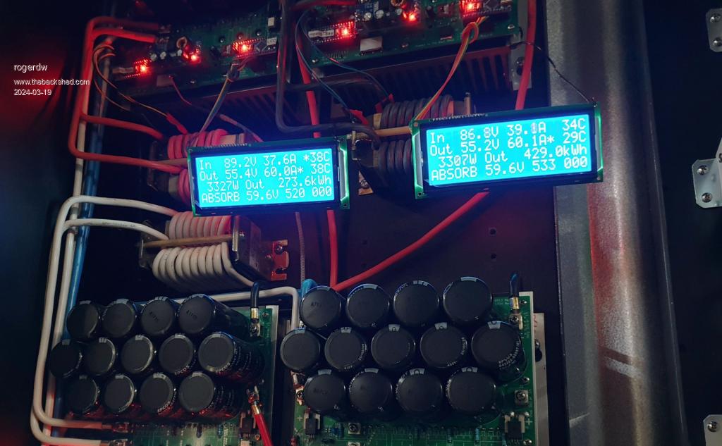
And to add insult to injury, here's a picture of the output from the first two mppt's going strong at one stage today, while the third was lagging behind. Had the camera at the wrong angle, so the third display didn't show. Not sure I should run it this hard ... but it was cloudy and only intermittant.
What's fascinating is that the first two lots of panels are old used 275 watt panels, two lots of 3.3kW ... and for short bursts they were pumping out just over that. I'm impressed. Great design, thanks man.

Senior Member
Joined: 12/09/2020
Location: United StatesPosts: 120
| Posted: 09:48pm 15 Apr 2024 |
Looks very nice!
What version of the MPPT board are you using? It looks a bit different from the one I referenced / built - you've got the Nano(s) on board!
Cheers,
R
Guru
Joined: 22/10/2019
Location: AustraliaPosts: 952
| Posted: 01:54am 16 Apr 2024 |
Thanks very much. It was one of Wiseguy's boards that (with his blessing and help) I added extra room on the bottom to fit both nano's and 12v and 5v supplies.
It was what I was working on way back here ... in this thread.
Like most things I do it took me forever to get it done and built but finally there now. I have all four up and pumping well and charging a 48v 980Ah forklift battery. And that is running my Warpverter.
Senior Member
Joined: 12/09/2020
Location: United StatesPosts: 120
| Posted: 03:02am 16 Apr 2024 |
Oh right, that one! Yes I remember that discussion. I'm glad it works nicely, good job!
R
Senior Member
Joined: 10/02/2015
Location: United KingdomPosts: 282
| Posted: 09:25pm 08 May 2024 |
Possibly spotted a very minor error in (i think) the latest version of the code.ZIP (serial LCD version):
TID=12027&P=47#212592latest version serial LCD
it seemed to do an extra MPPT scan every couple of mins at the 55sec mark ,but i spotted this in the code:
if ( timeout_check(8,1))
{
cal_sensor_count ++;
if (cal_sensor_count > 1) // should be 60 for an hour. testing will have it at 2 or something
{
cal_sensor_count = 0; // one hour is up time to recal current sensor zero points
if (track_mode != NIGHT)
{
//stop it
{
cal_sensor_count ++;
if (cal_sensor_count > 1) // should be 60 for an hour. testing will have it at 2 or something
{
cal_sensor_count = 0; // one hour is up time to recal current sensor zero points
if (track_mode != NIGHT)
{
//stop it
But as the Comment says "should be 60 for an hour" so is easy enough to change.
Guru
Joined: 02/02/2017
Location: AustraliaPosts: 1473
| Posted: 12:26am 09 May 2024 |
it's an easy fix alright. Thanks for reading through the code and finding this.
latest version with the fix:
mpptv5_BV_tempco_day_totals_current_sense_recal.zip
Guru
Joined: 17/10/2017
Location: BelgiumPosts: 474
| Posted: 08:24pm 11 May 2024 |
Hi Peter is there a reason you choose for the software serial instead of the already present hardware serial interface on the arduino board?
I ask because I want to add a can interface to the mppt controllers, I need pins 10 and 11 free for the spi bus. The idea was to add it on the nano that does the uart/I²C conversion for the display. The hardware should not conflict the spi bus, I'm not sure about the serial library.
Do you think this would work, or am I missing something?
Thanks.
Edited 2024-05-12 06:42 by nickskethisniks
Senior Member
Joined: 11/01/2024
Location: PolandPosts: 104
| Posted: 03:42pm 13 May 2024 |
Is there any update on this for mpptv5_highside_ntc version/serial lcd?
Guru
Joined: 22/10/2019
Location: AustraliaPosts: 952
| Posted: 09:10am 27 Nov 2025 |
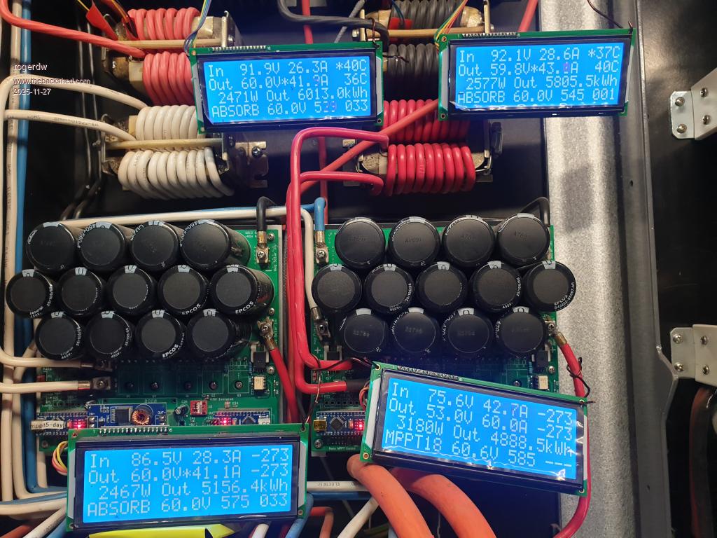
I know this thread hasn't been updated for a while, but thought I might upload a picture of my set of MPPTs and to thank Poida for an amazing project ... as well as Nicks and Wiseguy.
If you add it up you can see that combined they have generated 21,862kWh of power since being installed in March last year ... so 21 months.
Normally the outputs of all four are connected together to charge a couple of 48v forklift batteries ... but just at present I'm refurbing a 3rd battery and the 4th mppt is charging that on its own.
The top two are each fed by 3.3kW of panels ... two lots of 12 x 275W panels 3s4p
... and bottom two by 3kW each ... two lots of 12 x 250W 3s4p
As you can see I flog them pretty hard and have set them all to max 60A output and have never had any problem doing that.
The only time I have had issues was early in the piece when I turned off the outputs before I turned off the input from the panels. Doesn't seem to like that.
When it happens it blows the little batt volts - 12 volt converter and also once an optocoupler. If I switch them off correctly, no problems.
I added a tvr protection device to the inputs and a 13v zener on the outputs which seems to limit any damage.
Anyway, thanks guys for an amazing project ... and anyone considering building one, it's well worth it.
Guru
Joined: 02/02/2017
Location: AustraliaPosts: 1473
| Posted: 07:52am 29 Nov 2025 |
Roger,
good to see. I had to respond when reading you run them up to 60A.
no doubt they can do it.
how are the chokes and heatsink temps when doing this? are they reasonable?
In my experience, these MPPT just do the job.
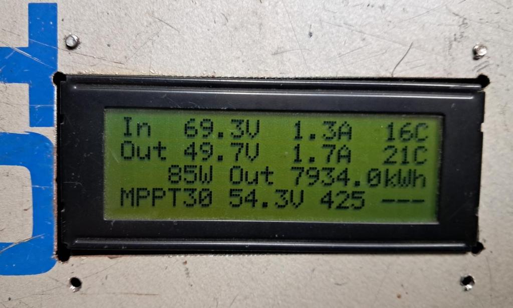
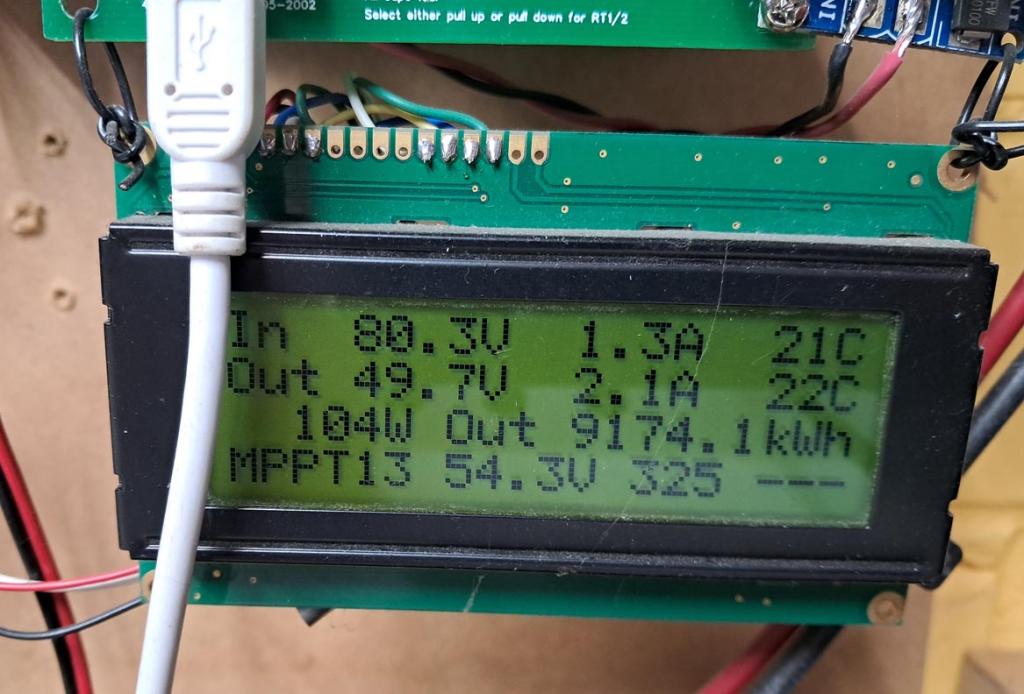
here are my 2, it's 7pm, cloudy in Melbourne.
Guru
Joined: 22/10/2019
Location: AustraliaPosts: 952
| Posted: 11:56am 29 Nov 2025 |
Peter, wow yours have clocked up some miles too.
Surprisingly the heatsinks never seem to get warm ... maybe a few degrees above ambient.
The chokes can warm up fairly quickly but I have a wide, single barrel fan across the bottom which is set to come on at 40C ... and shut off at 35C. The fan seems to keep them under control and doesn't get much above 40. You can hear it cut on and off during the day and doesn't seem to run long. It can start fairly early in the charge cycle too ... but again, doesn't have to run for super long periods.
It probably helps being all open but it's in a corrugated iron shed which can get pretty hot at times.
About the only thing I would like to have is the ability to make minor adjustments without having to break out the laptop and try and remember how to talk to it. I'm not all that familiar with Arduinos.
Thanks again. Guru
Joined: 02/02/2017
Location: AustraliaPosts: 1473
| Posted: 05:05am 30 Nov 2025 |
I have used a samsung phone, with usb cable and special USB plug/thing called an OTG adaptor.
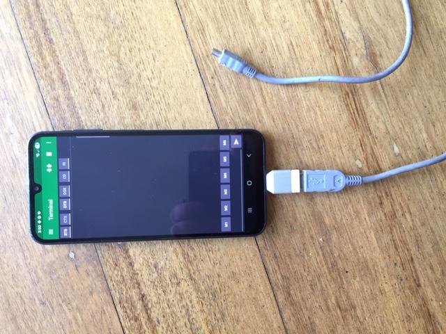
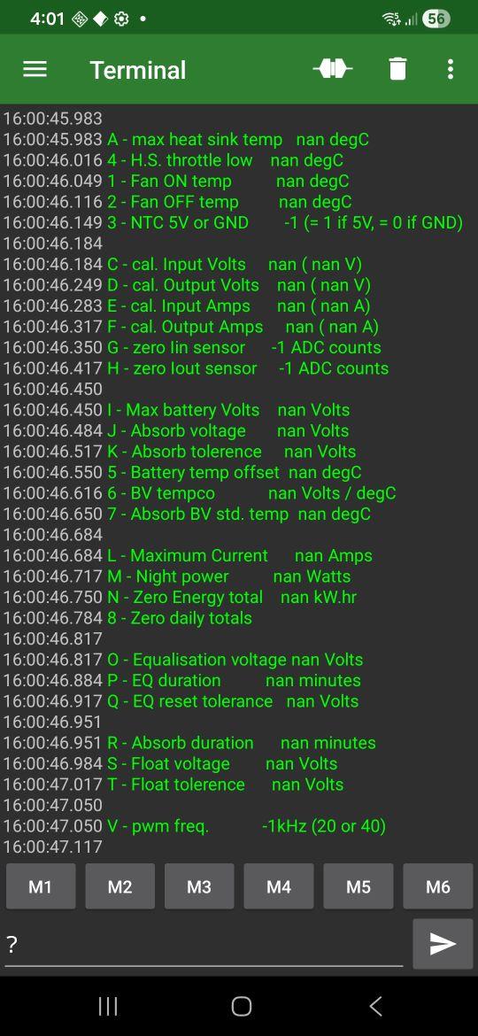
find and install "serial usb terminal"
config it to be
9600 baud, 8 bits, 1 stop, no parity
when sending, just "LF" as the newline terminator
choose to clear input on send
connect, send "?" and get the menu.
Edited 2025-11-30 15:08 by poida
Guru
Joined: 22/10/2019
Location: AustraliaPosts: 952
| Posted: 09:07am 30 Nov 2025 |
Thanks Peter, I had no idea that was possible.
I have a Samsung phone so I downloaded "serial usb terminal" and managed to find an OTG connector in the drawer.
You wrote "when sending, just "LF" as the newline terminator" which I didn't understand ... but found when I clicked the funny little symbol at the top ... a bit like a waveform with a gap in the middle ... it connected and recognised a legit target.
I was able to see the menu and make changes easily ... awesome.
Now that I'm rereading your comment I understand why you suggest "choose to clear input on send" ... otherwise you have to manually delete the previous command.
Well that's going to make any changes so much easier, thank you very much.
Newbie
Joined: 21/12/2024
Location: ArgentinaPosts: 1
| Posted: 12:21am 27 Apr 2026 |
Hello, my name is Diego. I've been reading the forum for a long time and I think the work you do is spectacular.
This has motivated me to install solar energy at my house. I have an MPPT that I bought, but it doesn't work at 48V. I bought it in September 2025, but I installed it a week ago and it's not working. I contacted the seller but didn't get a response, so while looking for information, I've read almost this entire thread. I have a question: what component is the DC-DC converter on this MPPT? Specifically, what do you use there? Thanks a lot! pdta mi ingles es de google
Edited 2026-04-29 08:22 by diego_z
Newbie
Joined: 21/04/2025
Location: AustraliaPosts: 24
| Posted: 01:19am 16 May 2026 |
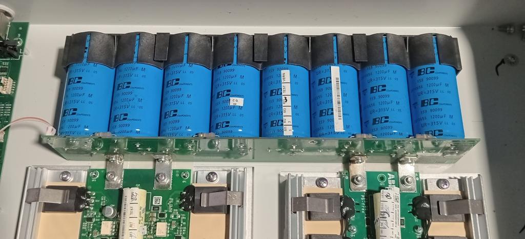
Can I confirm here that the following groups of capacitors would be usable for this build? You just install the required number to achieve or exceed the total design uF capacity - as previously indicated by Wiseguy? Or would this compromise the design?
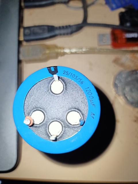
- 8 x 315V, 1200 uF, as pictured below from a 5 kW Aurora unit
- 11 x 315V, 1000 uF, from an SMA Sunny Boy.
- 5 x 315V, 1000 uF from an Aerosharp.
all presumed to be in working condition - I have not expertise or equipment to check.
all are 35mm diameter.
Realising now that I've previously scrapped many of these types of inverters - for copper and aluminium recovery- and threw out probably hundreds of suitable capacitors and mid sized transformer cores.
Edited 2026-05-16 11:20 by GleamBright
Guru
Joined: 13/10/2014
Location: AustraliaPosts: 2140
| Posted: 02:07am 16 May 2026 |
The capacitance values are not set in stone, they look good. You could test them with a current limited supply, but all the units I have removed were good quality with no faults, if there is no end cap swelling or case bulging then they are likely OK.

Guru
Joined: 31/12/2016
Location: AustraliaPosts: 1258
| Posted: 02:11am 16 May 2026 |
I have the exact same capacitors, they look good but you will need to check the data sheet as they have 4 connections at the bottom and at different diameter (hole spacing) good quality though.
Newbie
Joined: 21/04/2025
Location: AustraliaPosts: 24
| Posted: 07:47am 17 May 2026 |
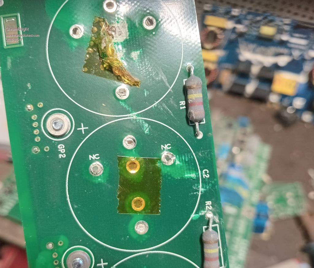
This is the PCB after cap removal & I checked online about four pin caps... the ports marked NC are 'not connected', for mechanical support only. Distance between pins is 22mm, do I just drill extra holes in the PCB for the NC pins?
Guru
Joined: 31/12/2016
Location: AustraliaPosts: 1258
| Posted: 12:14am 18 May 2026 |
I would probably remove the NC pins, seen as the 2 pins we want are 22mm apart there are options to find something else or deal with it, there might be some small lugs (available or make some) that can be soldered attached to those legs then through the PCB as normal, the PCB could be drilled to accommodate the cap legs as is but its a bit more work and troublesome in some positions......on the other hand we would only do this once and if done correctly would be well worth the little time spent compared to the cost and time waiting for new ones from some supplier over great distance.
There would need to be an insulating pad between the cap leads and the PCB (sil pad or something) then once installed into the PCB go around all the caps with some HY 704 silicon.
You have me interested now, I going to have ago at this when I get my other jobs done.

Guru
Joined: 11/02/2018
Location: AustraliaPosts: 3220
| Posted: 12:40am 18 May 2026 |
Accurately marking the holes could be streamlined with a template.
Firmly press the cap on to a piece of cardboard to make indentations.
Punch or drill holes at those locations to make the template.
Align the + and - holes with those on the PCB using pieces of wire, then mark the PCB through the NC holes.