
|
|
Forum Index : Electronics : 150V 45A MPPT - roll your own
| Author | Message | ||||
| rogerdw Guru Joined: 22/10/2019 Location: AustraliaPosts: 906 |
Yep ok, I'll stick my neck out. Bear in mind I'm new to this, it's the third board I've designed. I really only tackled this because I'd designed my Warpverter pcbs and then finding out how much the freight was going to be, figured I'd finish this off so I could include it with my order. Just being a cheapskate I suppose ... plus I enjoy learning new stuff. I was going to do what everyone else had done and create an add-on board, but then thought why not add on to the original board. With Wiseguy's blessing I started with his layout ... ... then added 33mm to the edge and stuck the Nano's ... the battery voltage to 5V converter ... and mounting holes for either of two size lcd displays. The idea is that it would then be totally stand alone and not need additional bits hanging off the sides. I recognise that I now have to use either 48v or 5v fans (or add another dc/dc converter) ... but even if I can't find any floating around in all my junk ... new ones at those voltages are not all that expensive ... a bit over $20 from element14 I expect I'll need to use two of these myself with my system when I finally get it completed. Yes I had seen it ... but by the time you popped back up with your finished and working version, I had already done most of my work ... so I kept going. If I hadn't already done that, I would have been happy to save my time re-inventing the wheel.  I just remembered another reason ... Poida mentioned that he'd only support the use of 2 x Nano's ... and me not being clued up enough to troubleshoot that on my own if I had problems ... decided up front to just follow his advice and stick to 2 Nano's. 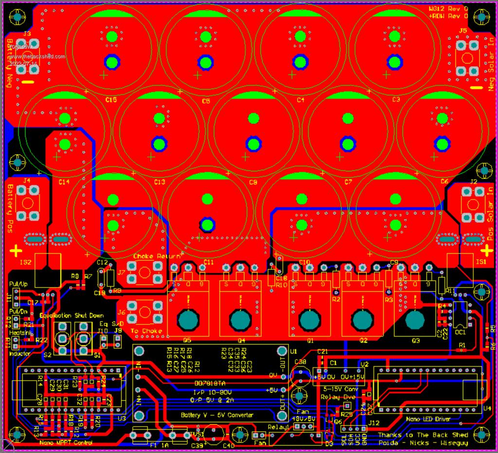 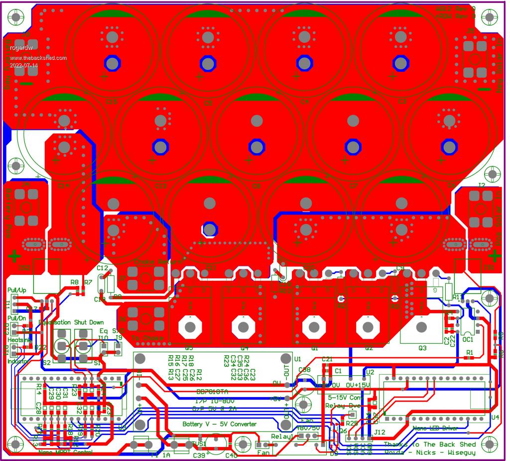 Cheers, Roger |
||||
| wiseguy Guru Joined: 21/06/2018 Location: AustraliaPosts: 1210 |
Well done Roger, good to see your results, well thought out. A few hopefully constructive comments; It would be good to see U4 with a supply decoupling cap right next to pins 27 & 29 like you did with U3. I'm not familiar with relay 1, ensure that the 2 output pins are large enough. I like your use of F1 - you can remove the fuse and power it up with something other than the output - which isn't there without batteries I always use ground-planes such as under the Nanos - if you need any help with it just holler, my contention is that the copper is already paid for, keep as much as possible! The 48V/5V selection for the fan is scary - a hard wired link might be the go. You're getting good at this - are you looking for more work....... If at first you dont succeed, I suggest you avoid sky diving.... Cheers Mike |
||||
| rogerdw Guru Joined: 22/10/2019 Location: AustraliaPosts: 906 |
Thanks for the encouragement Mike, I wasn't all that confident in posting it but glad I did in the end. As soon as I put it out there I went back in and changed heaps Ā... Ālots of things seemed to stand out that hadn't before. I was nearly going to edit my post and replace the images with the updates. C24 and C37 are across the input to U4 but were miles away Ā... Āso that's already fixed, thanks for pointing it out. The actual converter modules arrived yesterday and I had only guessed at the hole locations, they weren't supplied with the advert. I wasn't far out but now they are correct as well. I don't think they really need mounting holes with bolts Ā... ĀI'm pretty sure they could stand on the four connections Ā... Ājust a pity they're only 5mm apart. I hadn't considered the relay pin sizes, I'll go check that. Like you say, everything looks big in the program but when you check the actual sizes, they're miniscule. Regarding F1, I hadn't even thought of that Ā... ĀI was just covering my butt in case of blow-ups. ĀIf that converter fails, there has to be smoke somewhere and I'd like to allow for that rather than see tracks vapourise off the board.I'm a lot more comfortable with polygon pours now so I'll give it a go with ground planes under the Nano's. I think my reluctance with them comes from my daily work Ā... Āthere's a particular board I dislike working on because there's copper everywhere Ā... Āit's really difficult to fault find because you can't follow the tracks Ā... Āand they don't use any thermal relief for many of their vias, so really hard to desolder as well. Anyway, I'm learning. With the 48V/5V selection for the fan I was going to just fit a plug-on link Ā... Ādo you still think that's a bit risky or is it just the idea of soldering a wire across those pins which would be a huge risk. And am I looking for more work Ā... Āhaha, not sure I'm ready for that yet. Thanks for all your help. Edited 2022-07-15 13:33 by rogerdw Cheers, Roger |
||||
| rogerdw Guru Joined: 22/10/2019 Location: AustraliaPosts: 906 |
What are your suggestions Mike with the ground plane ... do I continue it up around the opto and around the switches on the left as well? And I assume I connect the net to ground and "pour over all same net objects"? 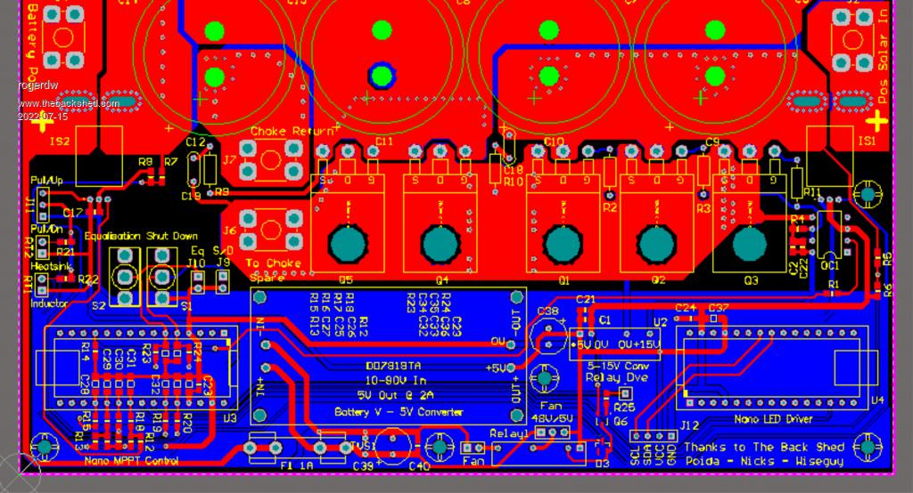 Cheers, Roger |
||||
| wiseguy Guru Joined: 21/06/2018 Location: AustraliaPosts: 1210 |
What you have done looks fine but it doesn't look like its connected to a net? ĀI am assuming you should name it the same net as the little power supply -out (dont forget to redraw the polygons each & every time you make any change to outline net name etc)? Why not do the same ground planing on the top layer too ? You can click on it, copy at a convenient corner and drag it to the side. Name the new polygon (same as original) and double click and change from bottom to top layer. It needs to be redrawn (select the top layer first - (bottom of screen)) and move the new top polygon on top of the other and redraw. Simple lol. The red top layer is too close to the edge of the pcb closest to the neg solar in. Most PCB houses prefer 15 mil from polygon or trace to edge of PCB. ĀMost of the large, bottom side and top side layers, were perfectly registered on top of each other originally - I'm not fussed but maybe something got moved you weren't intending? Unless you are using plastic standoffs be aware that you have provided two grounding points on the screw mount holes for the ground plane. I usually avoid doing this, by all means have a small island of copper under the screw and even provide pads for either a solid link or a capacitor to the ground planing. When high-ish currents are involved voltage drops can be coupled/introduced accidentally & if its noise that is then a problem you can always use a 100n ceramic or similar to help mitigate noise issues. You dont have to follow any of this - I'm not trying to impose my will on you, its all just free advice & suggestions Edited 2022-07-15 15:38 by wiseguy If at first you dont succeed, I suggest you avoid sky diving.... Cheers Mike |
||||
| wiseguy Guru Joined: 21/06/2018 Location: AustraliaPosts: 1210 |
If you are concerned about thermal reliefs for a topside ground plane to make smd parts easier to solder, and the rest of the design is direct connects without thermals I can help you achieve this. Its a bit of a pain but do-able. If at first you dont succeed, I suggest you avoid sky diving.... Cheers Mike |
||||
| Alston Regular Member Joined: 04/04/2021 Location: AustraliaPosts: 63 |
That looks great Roger! I would be keen to get the artwork when you have finished it and like you bundle up a few projects I need printed to cut down on postage. |
||||
| rogerdw Guru Joined: 22/10/2019 Location: AustraliaPosts: 906 |
You're right, I hadn't connected it to a net yet. It's a slow process.  I can do that ... and keep as much of the copper I'm paying for as possible. That last sentence covers it. Hey, what's this button for ...... three hours later I'm finally back where I started. Bit like this I guess this shows up just how much I don't know about board design. Fixing them yes, but designing, no! Thanks for the tutorials. Nope, I don't get that vibe at all ... just very happy to have some pointers to make this project as good as we can make it. Thank you again. Cheers, Roger |
||||
| rogerdw Guru Joined: 22/10/2019 Location: AustraliaPosts: 906 |
That sounds fair Alston though I have to point out that the originals were shared with me under the proviso they were for personal use and not for profit, so as long as that is acceptable I will let you know once I've finished. As I'm only on my L plates as far as board design goes, there may be issues with it so may be better to wait a little while until I've built one and know it works for sure. Would be expensive coasters if I've stuffed up.  Cheers, Roger |
||||
| rogerdw Guru Joined: 22/10/2019 Location: AustraliaPosts: 906 |
Okay, I think I have addressed all the points. Adjusted the polygons near the edges plus matched up the front and rear a little better. Checked the relay datasheet and increased the hole size for the switching pins. Thanks Mike, I woulda been at it with a drill to make it fit and defeat the purpose of plated through holes. Fitted the ground planes top and bottom and cleared space around the mounting holes. I also increased spacing around the 48V section of the fan relay and socket .. and changed D3 from a SOT-23 diode to a SOD123 1N4148. Looks a bit tidier. It's certainly harder to follow the layout with all the extra copper, so it was good to find out I could 'hide' the polygon pours while I was checking things ... though why they call it 'shelving' beats me. I spent ages looking for that command ... but when I'd shelved them, I couldn't right click on them so I could 'unshelve' them. Eventually I discovered the polygon manager and found I could untick them in there. No wonder this is taking weeks! I feel like a slow learner. 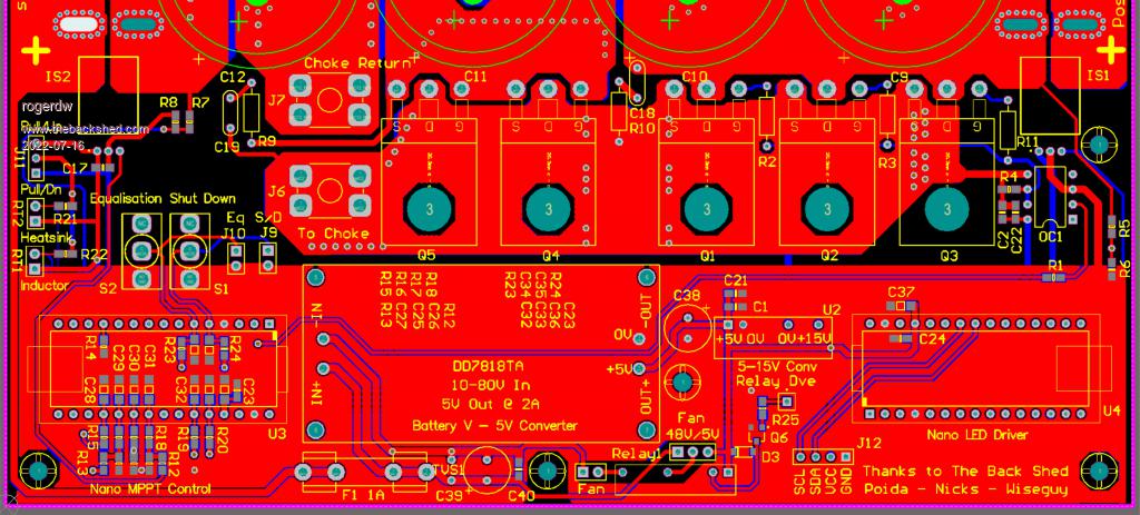 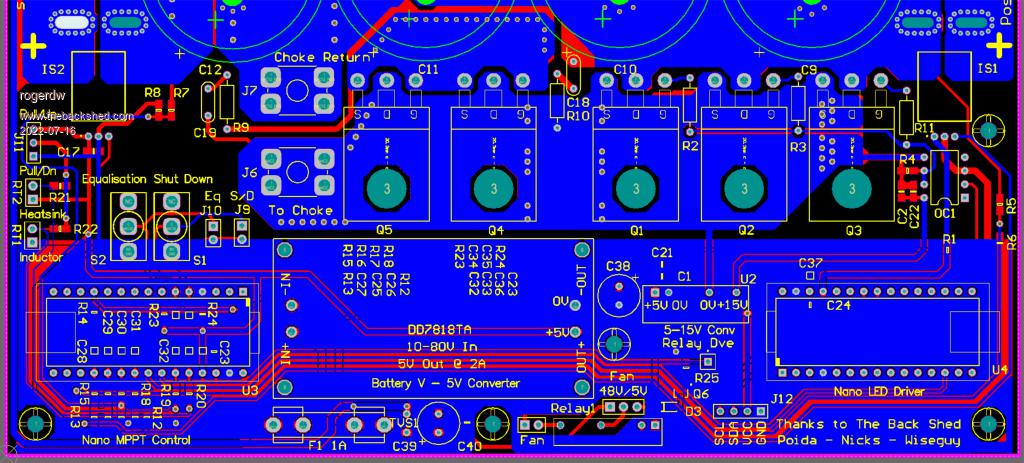 Cheers, Roger |
||||
| flyingfishfinger Senior Member Joined: 12/09/2020 Location: United StatesPosts: 118 |
This is very nice, good job! The 48V / 5V fan section concerns me, as others have mentioned - just go with 5V fans and don't worry about it, I say. What is U2 for, it looks like a 5V -> 15V boost converter? I didn't see a schematic and don't have time right now to trace out the functioning fully - but it seems that's your supply voltage for the opto. I see that you've foregone a 12V regulator completely and instead are running the whole thing on 5V, totally reasonable design choice and it would explain why you need another 15V source for the driver, am I correct? One other point of concern, but it might be a major change for a small-ish nitpick. Is the big 5V regulator isolated? If yes, then you have run your input ground through, and over the 5V ground plane from the bottom left edge, under the fuse, through one via. Electrically, it would be better to rotate that thing 90 degrees, so the IN- pin sits in the battery negative plane but you get a large gap underneath to separate it from the 5V / logic ground plane completely. The single ground connection via the ferrite ring on the original layout served a similar purpose You also have the fans connected to the IN- ground, but if you choose to run off of the 5V regulator then you have effectively bypassed the benefit of the insulated ground because you will be tapping "across" the DC DC converter, I would connect it to the 0V / low voltage ground. Anyway, if you like we can also look at the schematic - but up to you. This looks great! R |
||||
| rogerdw Guru Joined: 22/10/2019 Location: AustraliaPosts: 906 |
Thanks for the feedback R, I appreciate it. The reason I considered 48 volt fans is because they can then run straight off the 48V battery and require no power from a seperate converter. In this case the battery voltage to 5 volt converter has plenty of headroom, so 5v fans would be no problem. I likely will use 5v fans, but can you expand a bit more about why you are not so keen on using 48v ones? The 48v supply is already on the board and only an inch away from the relay. Oh, and that converter is not isolated ... it doesn't need to be does it ... you have me wondering now. I assumed its only job is to safely provide some lower voltage to run the electronics on the board. I certainly did consider a 12v version but then I would need to add a 5v regulator for the current sensors and the Nano's.U2 is a 5v-15v dc-dc isolated converter as we need an isolated supply to drive the optocoupler for the mosfet switching. This design uses Wiseguy's pcb layout that many others have used (and that you used too I assume from your photo) ... with an extra inch and a half added to the bottom to fit the Nano's and the circuit that others have fitted on a seperate board ... so the circuit is the same as the one that has been presented before of the mppt board and the brainboard. When I get back to my work pc, I'll post the circuits combined on the one page. It's messy coz I'm a beginner, but hopefully it'll fill in the gaps. I'll need to study your comments on the ground plane a bit more as I'm a bit lost there ... but bear in mind, that 80-5v converter is not isolated. If it's supposed to be ... then I'll have to make some modifications. Thanks again for your feedback. Cheers, Roger |
||||
| Solar Mike Guru Joined: 08/02/2015 Location: New ZealandPosts: 1162 |
Your 80-5v non-isolated converter will be fine, just make sure the CPU + low current 0v grounds only terminate at a single point at the output of the converter 0v, where it links to the high current power 0v rail. This will help prevent power rail noise spikes on the 0v connection affecting the cpu and any analog circuits. I normally use an 80-12v psu, followed by an analog 5v or 3v psu chip, this prevents the 5v rail having noise spikes, especially if you have op-amps or using the cpu ADC. I use the 12v rail for fans, relays and leds etc. where noise doesn't matter. Cheers Mike |
||||
| rogerdw Guru Joined: 22/10/2019 Location: AustraliaPosts: 906 |
Thanks Solar Mike, that's very helpful ... especially the second regulator effectively giving a second level of protection. I'm still of two minds ... the converters I bought come in 80-5V and 80-12V (plus others) and I could alter two resistors to change to whatever I want ... so I'm not married to the 5V O/P ... and I did buy some of each. These are the ones I bought. So if I did go for a 12V O/P ... what sort of 5V regulator setup (and relevant heatsink) would you recommend? I'm still trying to compute the concept about the "CPU + low current 0v grounds only terminate at a single point at the output of the converter 0v" Is that the same thing as Mike's (wiseguy) Quiet Ground and Noisy Ground description? I spent a few (maybe more than a few) hours yesterday redesigning the ground planes at the bottom, after a bit of coaching around the concept of 'ground planes'. So to add an extra 5V regulator should be no real issue.Thanks for your help. Cheers, Roger |
||||
| Murphy's friend Guru Joined: 04/10/2019 Location: AustraliaPosts: 671 |
Roger, I use these To get 5V from 12V No need to mess about with heatsinks |
||||
| Murphy's friend Guru Joined: 04/10/2019 Location: AustraliaPosts: 671 |
The link does not work in my post above and it does not let me correct it so I try again: these |
||||
| Murphy's friend Guru Joined: 04/10/2019 Location: AustraliaPosts: 671 |
Nah, no good, useless edit feature, I give up. |
||||
| rogerdw Guru Joined: 22/10/2019 Location: AustraliaPosts: 906 |
Thanks for the efforts Klaus ... for some reason your link still has "http://www.thebackshed.com/forum/" before the actual link ... so after deleting that part, it went through okay. I'll have a go now, try this here It's amazing what is available nowadays ... and so cheap too ... if we are patient enough to wait for the slow boat from China. These boards will have 2oz copper cladding, so soldering a regulator direct to a decent sized pad should be all that it needs maybe. Cheers, Roger |
||||
| Murphy's friend Guru Joined: 04/10/2019 Location: AustraliaPosts: 671 |
Thanks for fixing that link Roger, yes that is the one. 2oz boards? you must have deep pockets  . My MPPT uses a 1oz PCB and this handles 50Amp just fine. The power track layout is similar to yours. . My MPPT uses a 1oz PCB and this handles 50Amp just fine. The power track layout is similar to yours. |
||||
| Solar Mike Guru Joined: 08/02/2015 Location: New ZealandPosts: 1162 |
Check to make sure those small power supplies don't have a resistor in the output -ve connection, some use this for current limiting. If so then the output cannot be connected to the main battery 0v junction as it will short out the resistor. I use these with a Common 0v Line The 12-5v regulator chip; I use the common smd 3 terminal regulators and soldered to a small piece of pcb as the heatsink, at <100ma load they don't run hot. Probably same thing, here is an example where the main 0v copper pour has 60 + amps running in it, the 0v gnd plane connection to the CPU and low power circuits are separated by a 0.5mm gap back to the common Battery 0v connection. This keeps the noise down in the low power circuits. 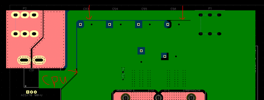 Cheers Mike |
||||
| The Back Shed's forum code is written, and hosted, in Australia. | © JAQ Software 2025 |
